Coupling welding equipment and method for coaxial collimator

A welding equipment and collimator technology, which is applied in welding equipment, laser welding equipment, metal processing equipment, etc., can solve the problem of unsuitable coupling and packaging of coaxial collimators, and achieves improved convenience and coupling accuracy. The effect of enhancing convenience

Active Publication Date: 2021-06-04
湖南中南鸿思自动化科技有限公司
View PDF14 Cites 7 Cited by
  • Summary
  • Abstract
  • Description
  • Claims
  • Application Information

AI Technical Summary

Problems solved by technology

Since the coaxial collimator needs to complete multiple annular welding of the fiber optic adapter, adjustment ring and lens, the device needs to be positioned vertically and coaxially to facilitate the circular operation of the welding torch, and multiple annular welding also brings new coupling and detection Difficulty, the above scheme is not suitable for coupling package of coaxial collimator

Method used


Image

  • Coupling welding equipment and method for coaxial collimator
  • Coupling welding equipment and method for coaxial collimator
  • Coupling welding equipment and method for coaxial collimator

Examples


Embodiment 1

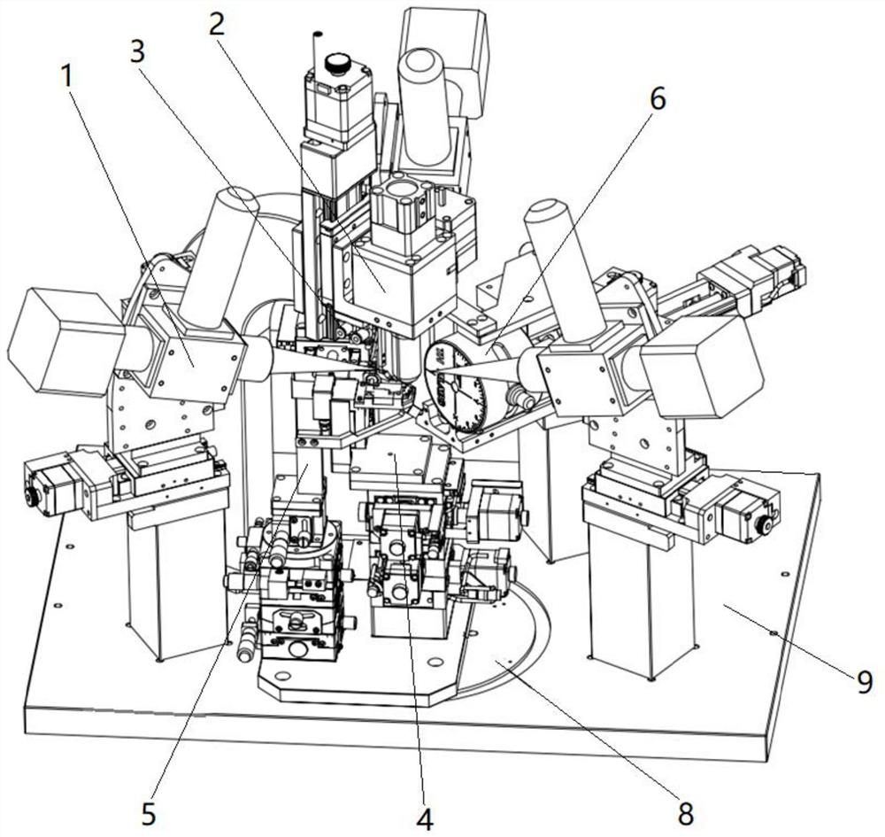
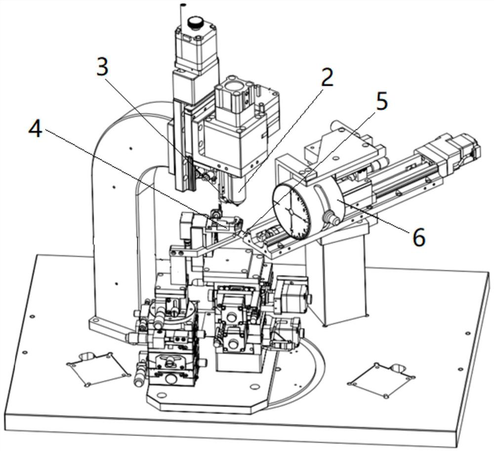
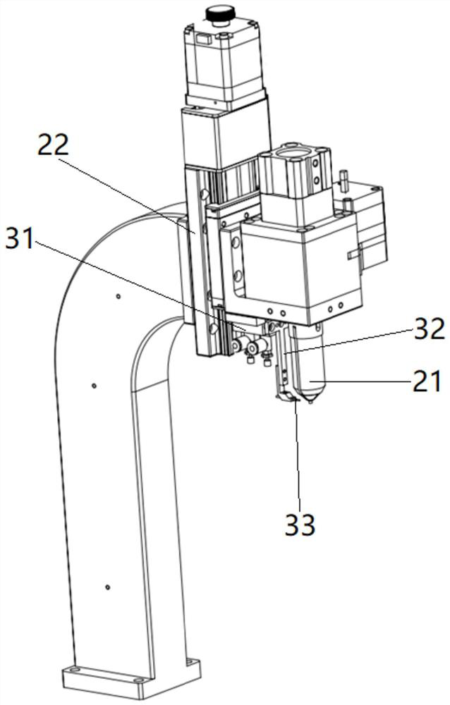
[0040] Such as figure 1 , figure 2 and Figure 8 As shown, Embodiment 1 of the present invention provides a coupling welding device for a coaxial collimator, including a laser welding torch assembly 1, an upper clamp assembly 2, an adjustment ring tightening assembly 3, a lens clamp assembly 4, and a mirror assembly 5 and detection analysis component 6. Among them, the upper clamp assembly 2 clamps and positions the optical fiber adapter 71, the lens clamp assembly 4 clamps and positions the lens 72, and the optical fiber adapter 71 is pre-set with an adjustment ring 73, and the adjustment ring 73 is tightened on the optical fiber adapter by the adjustment ring tightening assembly 3 71, the reflector assembly 5 has multiple degrees of freedom of movement. The reflector 51 is moved and positioned under the lens 72, so that the outgoing light energy of the lens 72 can be reflected to the detection and analysis assembly 6, so that the light spot can be detected by the detectio...

Embodiment 2

[0052] Embodiment 2 of the present invention provides a coupling welding method of a coaxial collimator, specifically comprising the following steps:

[0053] Step 1, feeding, the upper clamp assembly 2 clamps the optical fiber adapter 71 , the adjusting ring 73 is pre-sleeved on the optical fiber adapter 71 , the adjusting ring clamping assembly 3 clamps the adjusting ring 73 tightly, and the lens clamping assembly 4 clamps the lens 72 .

[0054] Step 2, the upper fixture assembly 2 is lowered to the coupling position, and the near-field light spot is initially coupled, and the size of the light spot is adjusted to an appropriate position by adjusting the Z-axis position, and the distance coupling between the optical fiber adapter 71 and the lens 72 is confirmed, and the outgoing light of the lens 72 is parallel light (Gaussian beam), adjust the X-axis and Y-axis positions of the beam profiler 61 through the two-axis displacement slide table 62, so that the spot moves to the c...


PUM


Abstract

The invention provides coupling welding equipment for a coaxial collimator. The coupling welding equipment comprises a laser welding gun assembly, an upper clamp assembly, an adjusting ring abutting assembly, a lens clamp assembly and a detection and analysis assembly, an optical fiber adapter is clamped and positioned by the upper clamp assembly, a lens is clamped and positioned by the lens clamp assembly, an adjusting ring is arranged on the optical fiber adapter in a sleeving manner, and the adjusting ring abuts against the optical fiber adapter through the adjusting ring abutting assembly; and the coupling welding device further comprises a reflecting mirror assembly which has multiple degrees of freedom of motion, a reflecting mirror is moved and positioned below the lens, and emergent light of the lens is reflected to the detection and analysis assembly. All devices of the collimator can be vertically and coaxially positioned, annular operation of the laser welding gun assembly is facilitated, a coaxial emergent light path is reflected to the detection and analysis assembly under the action of the reflecting mirror, the detection and analysis assembly can be horizontally arranged, it is ensured that an enough distance is reserved between a near-field position and a far-field position, and the equipment installation and arrangement convenience and the coupling accuracy are improved.

Description

technical field [0001] The invention relates to the technical field of collimator packaging, in particular to a coupling welding device and method for a coaxial collimator. Background technique [0002] The collimator is an optical element used for input and output of optical fiber communication optical devices. Its structure is relatively simple, including fiber optic adapters and lenses. The divergent light emitted by the optical fiber becomes parallel light (Gaussian beam) through the front lens. To couple light into the desired device with maximum efficiency or to receive light signals with maximum efficiency. In the coaxial collimator, the fiber optic adapter and the lens are located on the same optical path line. Based on the characteristics of the parallel light output, the fiber optic adapter and the lens need to be coupled and packaged by welding the adjustment ring. [0003] Patent CN111290088A discloses a lens coupling method and device for a light-emitting eleme...

Claims


Application Information

Patent Timeline
Patent Type & Authority Applications(China)
IPC IPC(8): B23K26/21B23K26/02B23K26/064
CPCB23K26/21B23K26/02B23K26/0643
Inventor 徐聪唐佳卢胜强
Owner 湖南中南鸿思自动化科技有限公司
Why Eureka
Try Eureka