

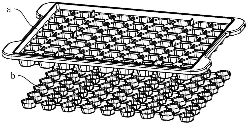
Ice-making box injection molding process and primary injection mold and secondary injection mold thereof
A technology of secondary injection molding and injection molding, which is applied to other household appliances, household appliances, household components, etc., can solve the problem of difficulty in taking out ice cubes, and achieve the effect of better product quality and easy automatic reset.
- Summary
- Abstract
- Description
- Claims
- Application Information
AI Technical Summary
Problems solved by technology
Method used
Image

Examples
Embodiment 1
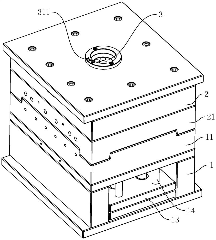
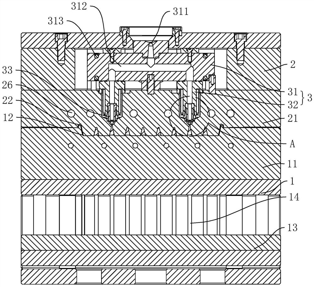
[0059] The embodiment of the present application discloses a one-shot injection mold. refer to figure 2 and image 3 , a one-time injection mold, including a fixed mold, a movable mold for fitting with the fixed mold, the fixed mold includes a fixed mold main body 2, a fixed template 21 fixed on the fixed mold main body 2, and the movable mold includes a movable mold main body 1 , the moving template 11 that is fixed on the moving mold main body 1. The fixed template 21 is provided with a mold groove 1 22, and the movable template 11 is provided with a mold groove 2 12. After the surfaces of the fixed template 21 and the fixed template 21 are attached, the mold groove 1 22 and the mold groove 2 12 are combined to form a mold cavity. The main body 2 is provided with a pouring structure 3 for pouring glue into the cavity. The injection molding machine can inject glue into the cavity through the pouring structure 3 to complete the molding of the workpiece.
[0060] The pouri...
Embodiment 2
[0076] The difference between this embodiment and embodiment 1 is: refer to Figure 8 The ejector rod 241 located in the installation blind hole 1 23 is provided with a rotating end block 246, an air pressure channel 247, and an air pressure groove 248. The ejector rod 241 is away from the end of the blind hole-23 bottom wall and is rotatably connected. The rotating shaft of the rotating end block 246 is coaxial with the axis of the ejector rod 241. The air pressure groove 248 is positioned at the end of the ejector rod 241. The rotating end block 246 The air pressure groove 248 is closed towards the side wall of the ejector rod 241. The length direction of the air pressure channel 247 is along the length direction of the ejector rod 241. One end of the air pressure channel 247 is connected to the bottom wall of the air pressure groove 248, and the other end is connected to the ejector rod. 241 faces the sidewall of the vent hole 25 to communicate with the vent hole 25 .
[0...
PUM
 Abstract
Description
Claims
Application Information