
Office keyboard key printing equipment

A kind of printing equipment and office technology, which is applied in the field of key printing equipment on office keyboards, which can solve the problems of manpower consumption, difficult collection of keyboards, and inability to locate keyboards, and achieve the effect of improving printing efficiency and facilitating collection by sliding down

Active Publication Date: 2021-06-04
成都戴德网络科技有限公司
View PDF13 Cites 5 Cited by
  • Summary
  • Abstract
  • Description
  • Claims
  • Application Information

AI Technical Summary

Problems solved by technology

[0005] In order to overcome the shortcomings of the prior art that the keyboard cannot be positioned, manual loading and unloading, labor-intensive, and difficult to collect the keyboard, the technical problem of the present invention is to provide a simple operation to complete the printing of the keyboard keys, automatically quantitatively load the material sequentially, and automatically push out the keyboard. On-key printing equipment for office keyboards for easy keyboard slide-off collection

Method used


Image

  • Office keyboard key printing equipment
  • Office keyboard key printing equipment
  • Office keyboard key printing equipment

Examples


Embodiment 1

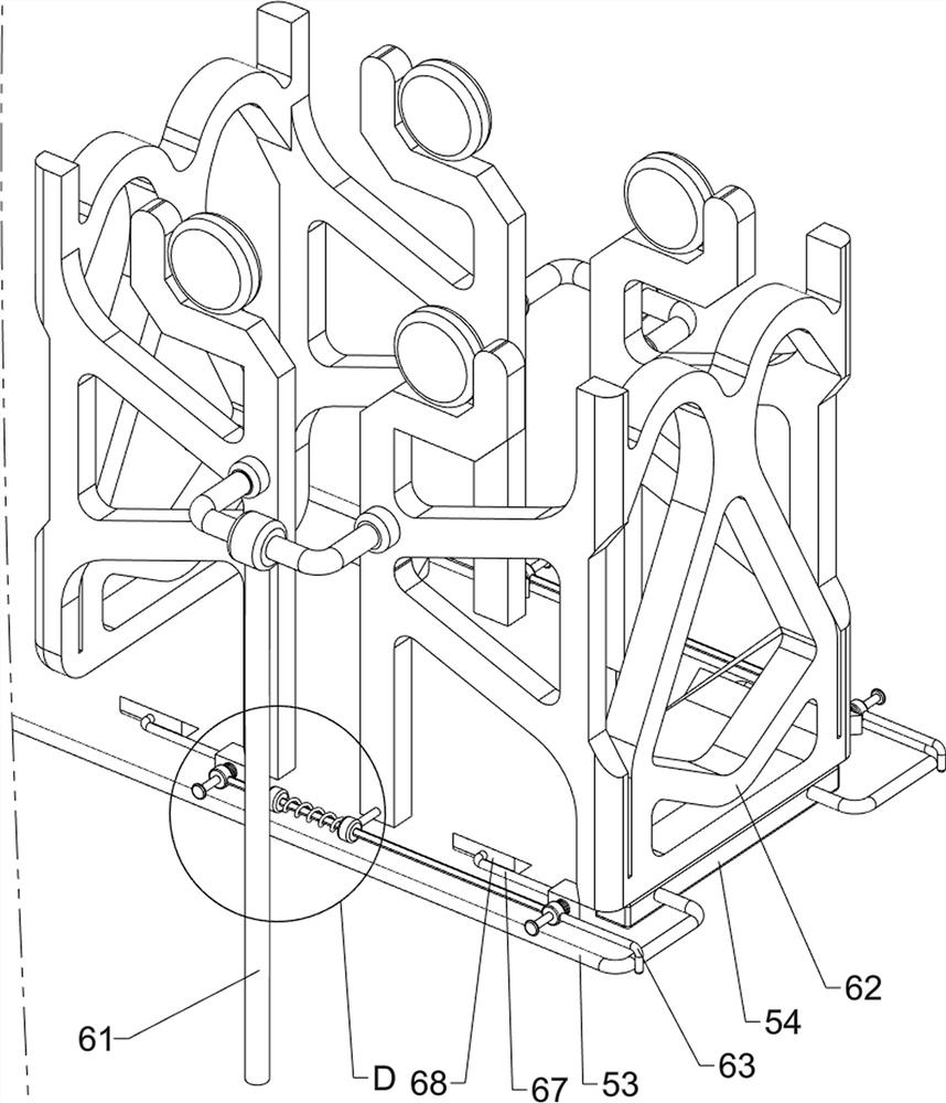
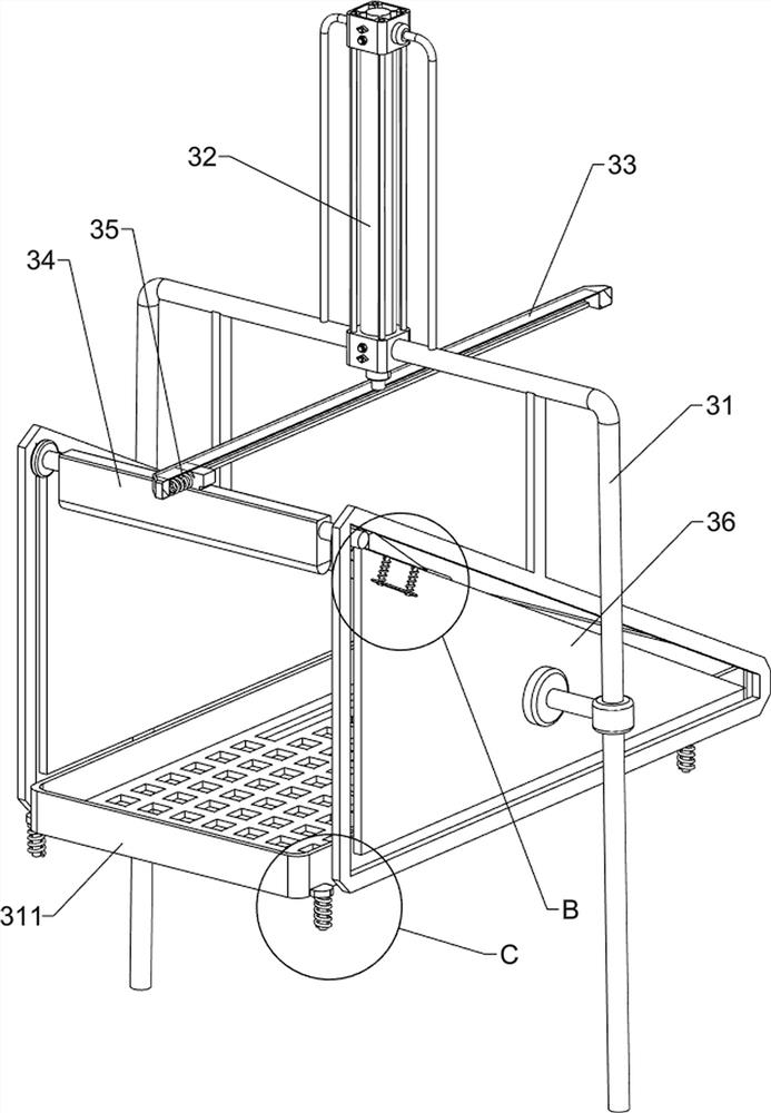
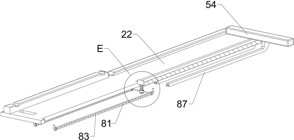
[0036] A key printing device on a keyboard for office use, such as figure 1 , figure 2 , image 3 , Figure 4 , Figure 5 with Image 6 As shown, it includes a base 1 , a placing component 2 and a printing component 3 , the placing component 2 is arranged on the upper part of the base 1 , and the printing component 3 is arranged between the left side of the upper part of the base 1 and the placing component 2 .

[0037]The placement assembly 2 includes a first support frame 21, a placement plate 22, a first baffle plate 23, a first guide rod 24, a first wedge block 25 and a first spring 26, the top of the base 1 is connected with the first support frame 21, the first A support frame 21 top is connected with a placement plate 22, the left side of the top of the placement plate 22 is connected with a first baffle plate 23 symmetrically front and rear, and the middle of the top of the placement plate 22 is connected with a first guide rod 24 in a symmetrical front and back s...

Embodiment 2

[0041] On the basis of Example 1, such as figure 1 , Figure 7 , Figure 8 , Figure 9 , Figure 10 , Figure 11 , Figure 12 and Figure 13 As shown, a positioning assembly 4 is also included, and the positioning assembly 4 includes a fourth guide rod 41, a stopper 42 and a fifth spring 43, and a pair of fourth guide rods 41 are connected symmetrically front and rear on the left side of the bottom of the placement plate 22. The four guide rods 41 are all symmetrical front and back, every pair of fourth guide rods 41 upper sides are slidably connected with stoppers 42, the stoppers 42 are slidably connected with the placement plate 22, and the front and back of the stoppers 42 and the placement plate 22 are all slidably connected. A fifth spring 43 is symmetrically connected, and the fifth spring 43 is sleeved on the fourth guide rod 41 .

[0042] When the keyboard is pushed from the right side to the underside of the paint plate 311, it is blocked by the stopper 42 and...


PUM


Abstract

The invention relates to printing equipment, in particular to office keyboard key printing equipment. The office keyboard key printing equipment which can complete keyboard key printing through simple operation, automatically, sequentially and quantitatively feed, automatically push out a keyboard and conveniently slide down the keyboard and collect the keyboard is provided. According to the technical solution, the office keyboard key printing equipment comprises a base and a printing assembly, wherein a placing assembly is arranged on the upper portion of the base, the printing assembly is arranged between one side of the upper portion of the base and the placing assembly. According to the office keyboard key printing equipment, a first connecting rod moves leftwards to be away from a second connecting rod, under the action of a sixth spring and a seventh spring, a third wedge-shaped block is pushed to move towards the left inner side, a fourth wedge-shaped block is driven to move towards the left inner side, remaining keyboards are ejected up, the effects of facilitating feeding and automatically and quantitatively feeding in sequence are achieved, and the printing efficiency is improved.

Description

technical field [0001] The invention relates to a printing device, in particular to a key printing device on an office keyboard. Background technique [0002] In modern society, computers are playing an increasingly important role. In office work, computers are an indispensable tool for assisting work. There are words on the keys on the keyboard paired with the computer, which instruct people to operate. The characters are all printed. [0003] The existing key printing technology on the keyboard is to manually push the keyboard under the paint board by the user. Under the existing technology, after the paint board is driven down to press the keyboard, the scraper moves on the paint board to complete the printing. Then manually push the keyboard away for collection. When the keyboard is first pushed to the underside of the coating board, there is no positioning part, and the position of the keyboard cannot be determined. The manual loading and unloading is a complicated pro...

Claims


Application Information

Patent Timeline
IPC IPC(8): B41F17/00H01H13/88H01H11/00
CPCB41F17/00H01H13/88H01H11/00B41P2217/10B41P2217/50Y02P70/10
Inventor 段运军
Owner 成都戴德网络科技有限公司
Learn More