
A new type of air storage tube device and ballast hopper car

A funnel car and air storage technology, which is applied in the field of railway freight cars, can solve the problems of difficult maintenance of transmission accessories such as two-way air cylinders, difficult operation of ballast unloading flow control devices, volume and self-heaviness of air storage cylinders, etc., and achieves diversified installation methods , Improve the safety of use and application, and the effect of light weight

Active Publication Date: 2022-05-10
CRRC TAIYUAN CO LTD
View PDF0 Cites 0 Cited by
  • Summary
  • Abstract
  • Description
  • Claims
  • Application Information

AI Technical Summary

Problems solved by technology

[0003] (1) Due to the size and weight of the air storage tube, it is difficult to carry it in and out through the control room end and side door, and it is extremely inconvenient to install and disassemble, and because it is installed obliquely on the two diagonal braces in the center of the end wall of the control room, it occupies the middle space of the control room There are too many positions, making it difficult for maintenance personnel to enter the control room to check the two-way air cylinder and other transmission accessories, and the maintenance time is relatively long, which affects the efficiency of temporary maintenance in use and factory and section maintenance.
[0004] (2) With the advancement of technology and the application of new technologies, customers gradually require new technologies such as bottom door opening display and ballast unloading flow control device to be added to the upper transmission device in the control room. Block the observation line of sight, and it is not easy to operate the ballast unloading flow control device

Method used


Image

  • A new type of air storage tube device and ballast hopper car
  • A new type of air storage tube device and ballast hopper car
  • A new type of air storage tube device and ballast hopper car

Examples


Embodiment Construction

[0062]Preferred embodiments of the present invention will be described in more detail below. Although preferred embodiments of the present invention are described below, it should be understood that the present invention can be embodied in various forms and should not be limited by the embodiments set forth herein. Rather, these embodiments are provided so that this disclosure will be thorough and complete, and will fully convey the scope of the invention to those skilled in the art.

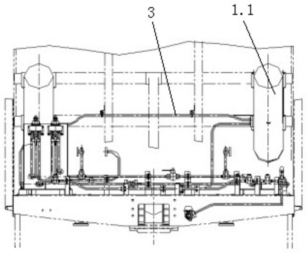
[0063] image 3 A structural schematic diagram showing a front view of a novel air storage device according to an embodiment of the present invention; Figure 4 It shows a structural schematic diagram of a left view of a novel air storage cylinder device according to an embodiment of the present invention; Figure 5 shows a novel air storage tube device according to an embodiment of the present invention Figure 4 Enlarged view of A.

[0064] Such as Figure 3-5 As shown, a new type of air ...


PUM


Abstract

The invention discloses a novel air storage cylinder device and a ballast hopper car, two mounting seats are arranged on the end wall belt of the operation room of the ballast hopper car, and two air storage cylinders are respectively arranged on the two mounting seats On the top, the double-hole flange interface is arranged on at least one air storage cylinder, and the flexible steel elbow is connected to one of the double-hole flange interfaces on one air storage cylinder, and the other end is connected to another air storage cylinder. Pipe, communicated with the other interface in the double-hole flange interface, the air storage tube device divides the existing single air storage tube into two, and uses two air storage tubes with the same volume as the existing single air storage tube , small size, light weight, flexible transfer, convenient assembly and disassembly, effectively saving the operating space inside the control room, which greatly facilitates the assembly, maintenance and other new technology applications of wind control, transmission, etc., and through the double-hole flange The interface reduces the leakage point of the connecting pipeline, further improving the reliability.

Description

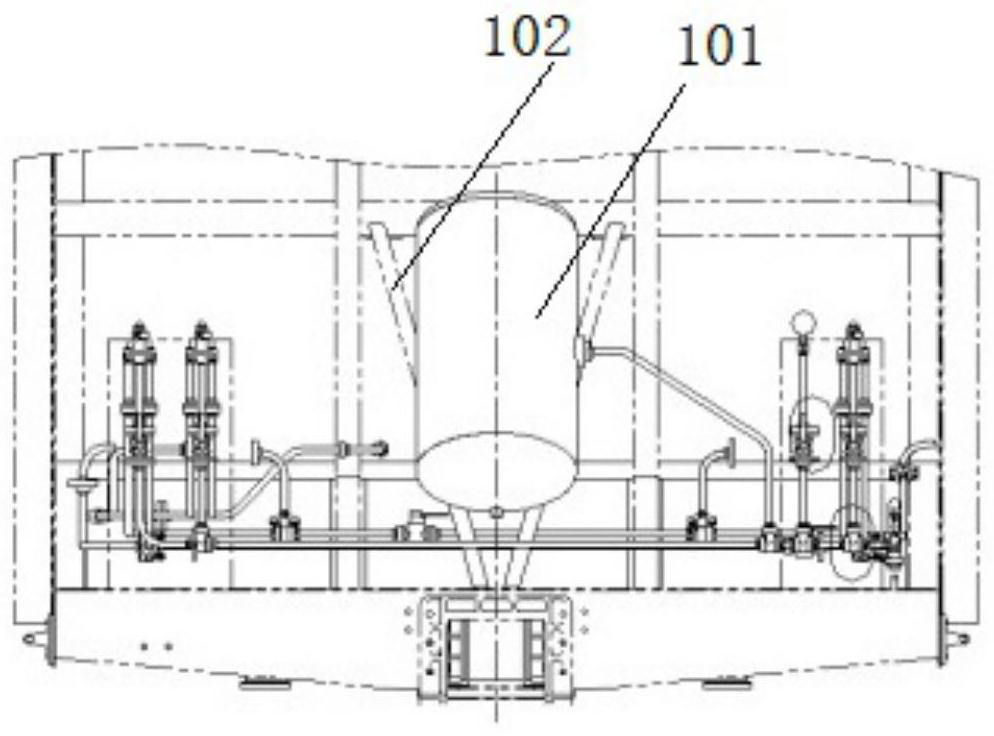
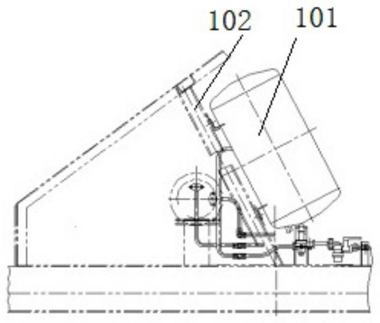
technical field [0001] The invention belongs to the technical field of railway wagons, and more specifically relates to a novel air storage tube device and a ballast hopper car. Background technique [0002] At present, the control room space of the railway ballast hopper car is relatively small, so the arrangement of the transmission device and the wind control device inside it is very compact. The air storage cylinder of the wind control device is installed obliquely on the two diagonal braces in the center of the end wall of the control room, as shown in the figure. Figure 1-2 As shown, and the wind control console, reducer and transmission shaft are arranged on both sides of it, which makes the space in the original control room narrower, and has the following problems and shortcomings: [0003] (1) Due to the size and weight of the air storage tube, it is difficult to carry it in and out through the control room end and side door, and it is extremely inconvenient to ins...

Claims


Application Information

Patent Timeline
Patent Type & Authority Patents(China)
IPC IPC(8): B61D7/28
CPCB61D7/28
Inventor 袁太红李云霞赵祖兴李旭英黄刚强冯凯魏文超郭欢张蓓刘文胜
Owner CRRC TAIYUAN CO LTD
Learn More