
Combined valve rod sealing structure

A technology of sealing structure and combined sealing, applied in the direction of valve shell structure, shaft seal, valve details, etc., can solve the problems of insufficient packing seal pressing force, damage to packing seal pressing force, damage to lip seal, etc.

Pending Publication Date: 2021-06-04
FOSHAN DAMANSEN SEALING TECH CO LTD
View PDF0 Cites 0 Cited by
  • Summary
  • Abstract
  • Description
  • Claims
  • Application Information

AI Technical Summary

Problems solved by technology

The simple combination of the two sealing forms will interfere with each other, because the applied pressure of the packing seal acts on the back of the lip seal, which may destroy the normal working conditions of the lip seal, causing premature damage to the lip seal, and the lip opening of the lip seal will be damaged. The compression force of the packing seal is destroyed, so that the compression force of the packing seal is insufficient, and the simple combination cannot give full play to the advantages of the two to achieve the effect of prolonging the service life

Method used


Image

  • Combined valve rod sealing structure
  • Combined valve rod sealing structure

Examples


Embodiment 1

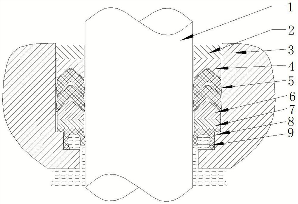
[0024] Such as figure 1 As shown: this embodiment provides a combined valve stem sealing structure 100, including packing gland 2, lip sealing ring 9, packing sealing assembly and isolation elements, between the valve stem 1 and the valve body 3 in order from top to bottom A packing gland 2 , a packing seal assembly, an isolation element and a lip sealing ring 9 are pierced, and the isolation element is clamped on the valve body 3 or the valve stem 1 . The packing gland 2 is threadedly connected with the valve stem 1, or the valve body 3 is additionally bolted to compress the packing gland 2.

[0025] The isolation element is a metal retaining ring 7, and the valve body 3 or the valve stem 1 is provided with a boss 8, and the metal retaining ring 7 is snapped on the boss 8, and if the lip sealing ring 9 has lugs, the lugs are also snapped On the boss 8, it is convenient to press and fix the lip sealing ring 9. Between the packing seal components of the isolation element, the...

Embodiment 2

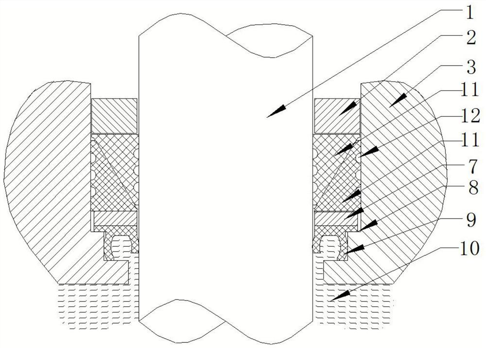
[0029] Such as figure 2 As shown: this embodiment provides a combined valve stem sealing structure 100, the only difference from the structure in the first embodiment is that the packing seal assembly is a wedge-shaped combined seal, and the wedge-shaped combined seal includes two matching wedge-shaped seal rings 11 , there are several ring grooves 12 on the contact surface between the wedge-shaped sealing ring 11 and the valve body 3 or valve stem 1, so that the contact surface changes from surface contact to line contact, and the sealing material can be filled with greater deformation under the same force For local gaps, the ring groove 12 can also divide one sealing surface into multiple seals to improve the sealing effect.


PUM


Abstract

The invention discloses a combined valve rod sealing structure which comprises a packing gland, a lip sealing ring, a packing sealing assembly and an isolating element. The packing gland, the packing sealing assembly, the isolating element and the lip sealing ring are sequentially arranged between a valve rod and a valve body in a penetrating mode from top to bottom, and the isolating element is connected to the valve body or the valve rod in a clamped mode. The friction coefficient is small, the friction loss of the sealing element is small, and the service life of the sealing element is long; the rotating torque of the valve rod is small, and the manufacturing cost of a driving device can be reduced in a self-control valve; the installation is simple, and maintenance is not needed; and the sealing effect of the lip sealing ring is good under high pressure, the packing sealing assembly makes up the defect that the sealing effect of the lip sealing ring is poor under the low-pressure working condition, and the lip sealing ring and the packing sealing assembly work independently and supplement each other and can be suitable for the working conditions of high temperature, low temperature and high-low temperature circulation.

Description

technical field [0001] The invention relates to the technical field of sealing structures, in particular to a combined valve stem sealing structure. Background technique [0002] Stem seal refers to the sealing device installed between the valve body and the operating valve stem to prevent the fluid in the valve from leaking from the gap between the valve body and the valve stem. The valve stem seal usually adopts packing seal or lip seal. The packing seal uses external pressure to compact the packing to eliminate the gap between the valve stem and the valve body to achieve the sealing effect. The advantages are simple structure, low price and wide range of materials, and the loss of the seal can be compensated by adjusting the packing gland pressing force. The disadvantage is that the material is exposed to high temperature. Under working conditions, after expansion, the compression force is large, and the friction is large. The packing is easy to wear, and after cooling an...

Claims


Application Information

Patent Timeline
IPC IPC(8): F16K41/02F16K27/08
CPCF16K41/02F16K27/08
Inventor 胡承华唐欣杨小钢李庆娃
Owner FOSHAN DAMANSEN SEALING TECH CO LTD
Learn More