An infrared thermometer equipped with a rapid cooling mechanism
An Infrared Thermometer, Rapid Cooling Technology
- Summary
- Abstract
- Description
- Claims
- Application Information
AI Technical Summary
Problems solved by technology
Method used
Image
Examples
Embodiment 1
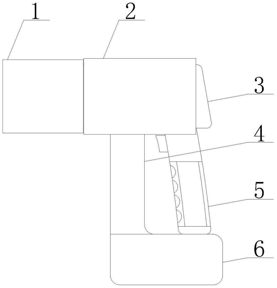
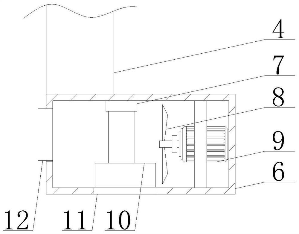
[0032] Such as figure 1 - Figure 7 As shown, the present invention provides an infrared thermometer with a rapid cooling mechanism, including a temperature measuring gun body 3, a protective connecting plate 4 and a handle 5, and the bottom edge of the temperature measuring gun body 3 is fixedly connected with a handle 5, The bottom of the temperature measuring gun body 3 is fixedly connected with a protective connecting plate 4, and the outer wall of the left end of the temperature measuring gun body 3 is movably socketed with a wind cooling frame 1, and the surface of the wind cooling frame 1 is provided with a ventilation hole 22, and the ventilation hole 22 The inner wall is fixed with an elastic connecting rope 32, the outer wall of the temperature measuring gun body 3 is slidably connected with the protective cover 2, the bottom of the protective cover 2 is provided with a card interface 25, and the outer wall of the protective cover 2 is provided with a second groove 2...
Embodiment 2
[0034] Such as Figure 4-5As shown, on the basis of Embodiment 1, the present invention provides a technical solution: a placement groove 30 is provided at the left central position of the buffer block 23, and an airbag 31 is fixedly connected to the side of the placement groove 30, and the side surface of the airbag 31 is connected to the The inner wall of the second groove 24 is fixedly connected, the left side of the buffer block 23 and the top of the placement groove 30 are provided with a buffer groove 27, the inner wall of the buffer groove 27 is fixedly connected with a fixed clamp 29, and the side of the fixed clamp 29 is hinged. Connecting rod 28 is arranged, and the other end of connecting rod 28 is hinged with buffer slide 26, and the side of buffer slide 26 is slidably connected with the inner wall of second groove 24, and buffer slide 26 and connecting rod 28 are all along the fixed clip 29. The position of the centerline of the airbag 31 is arranged symmetrically...
Embodiment 3
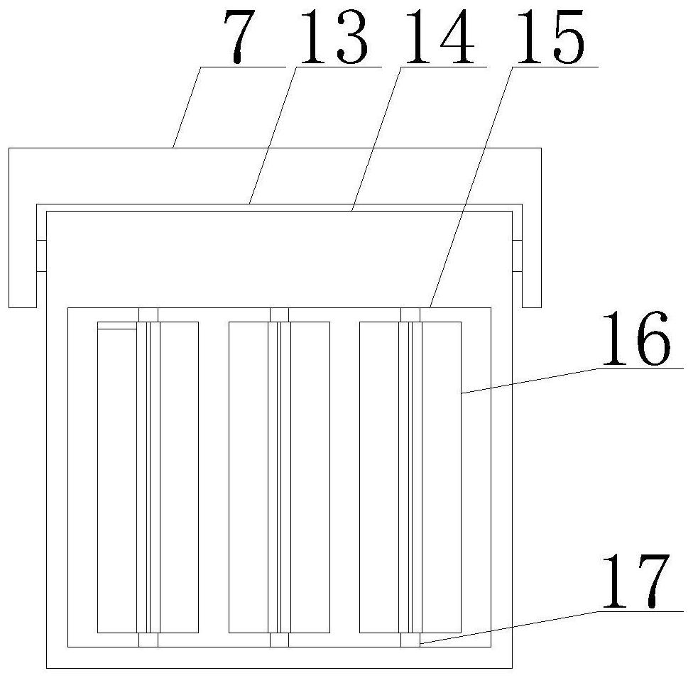
[0036] Such as Figure 6-7 As shown, on the basis of Embodiment 1 and Embodiment 2, the present invention provides a technical solution: preferably, the bottom of the fixed plate 7 is provided with a rotating groove 13, and the inner wall of the rotating groove 13 is fixedly connected with a movable block 14, which can be moved The outer wall of block 14 is slidably connected with the inwall of disinfectant solution placement box 10, and movable block 14 is arranged on the left side of fan 8, and the front of movable block 14 is provided with first groove 15, and the inwall of first groove 15 is rotatably connected with resistant The corrosion-resistant fixed shaft 17, the outer wall of the corrosion-resistant fixed shaft 17 is fixedly connected with a polymer diffusion plate 16, the polymer diffusion plate 16 is arranged on the right side of the atomization liquid outlet 12, and the polymer diffusion plate 16 is along the corrosion-resistant fixed shaft 17 The axial center li...
PUM
 Abstract
Description
Claims
Application Information
 - R&D
- Intellectual Property
- Life Sciences
- Materials
- Tech Scout
- Unparalleled Data Quality
- Higher Quality Content
- 60% Fewer Hallucinations
Browse by: Latest US Patents, China's latest patents, Technical Efficacy Thesaurus, Application Domain, Technology Topic, Popular Technical Reports.
© 2025 PatSnap. All rights reserved.Legal|Privacy policy|Modern Slavery Act Transparency Statement|Sitemap|About US| Contact US: help@patsnap.com


