Eureka AIR delivers breakthrough ideas for toughest innovation challenges, trusted by R&D personnel around the world.

Beam-focusing position calibration device for opposite penetrating type laser measuring instrument

A calibration device and laser measurement technology, which is applied to radio wave measurement systems, instruments, etc., can solve the problems of inaccurate calibration position of naked eyes, misalignment of deflection and misalignment of light, and low precision.

Pending Publication Date: 2021-06-04
HUANENG BEIJING CO GENERATION
View PDF6 Cites 0 Cited by
  • Summary
  • Abstract
  • Description
  • Claims
  • Application Information

AI Technical Summary

Problems solved by technology

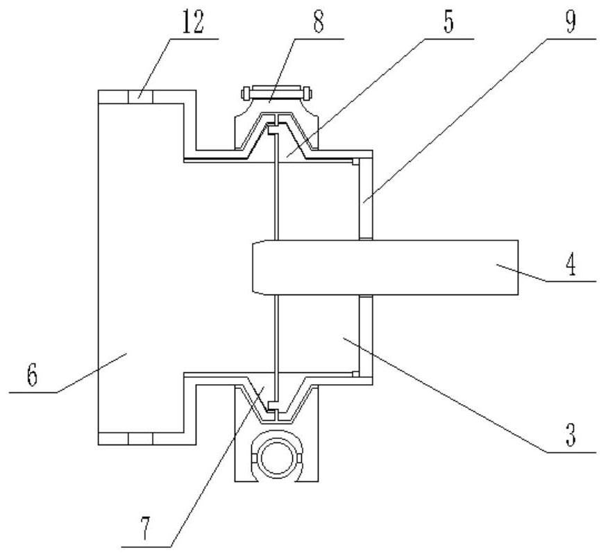
Among them, the positions of the transmitting end and the reflecting end of the instrument are often skewed and misaligned due to thermal expansion, vibration, etc. on the job site, which may easily cause measurement errors. It is necessary to adjust the positions of the transmitting end and the reflecting end of the instrument. However, in the prior art , there is no light position calibration device for the penetrating laser measurement method, and the staff need to calibrate with the naked eye, but the naked eye calibration position is not accurate and the accuracy is not high

Method used


Image

  • Beam-focusing position calibration device for opposite penetrating type laser measuring instrument
  • Beam-focusing position calibration device for opposite penetrating type laser measuring instrument
  • Beam-focusing position calibration device for opposite penetrating type laser measuring instrument

Examples


Embodiment Construction

[0040] The following will clearly and completely describe the technical solutions in the embodiments of the present specification in conjunction with the accompanying drawings in the embodiments of the present specification. Obviously, the described embodiments are only some embodiments of the present invention, not all embodiments. Based on the embodiments of the present invention, all other embodiments obtained by persons of ordinary skill in the art without making creative efforts belong to the protection scope of the present invention.

[0041] It should be noted that the terms "include" and "have" in the embodiments of this specification and the drawings, as well as any variations thereof, are intended to cover non-exclusive inclusion. For example, a process, method, system, product or device comprising a series of steps or units is not limited to the listed steps or units, but optionally also includes unlisted steps or units, or optionally further includes For other step...


PUM


Abstract

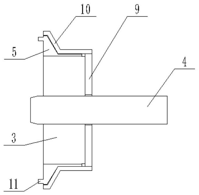
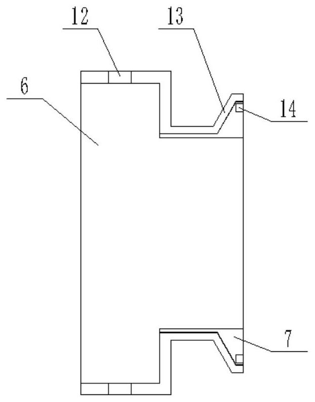
The embodiment of the invention provides a beam-focusing position calibration device for an opposite penetrating type laser measuring instrument, the beam-focusing position calibration device comprises a laser emitting device and a receiving calibration device, the laser emitting device is clamped in a first annular clamping groove through a first annular clamping block, a laser emitting mounting part and a laser emitting connecting part are positioned, the first clamping part and the second clamping part are clamped and fixed in the first clamping groove of the first pipe hoop, so that the laser emission mounting part is fixedly connected with the laser emission connecting part; a second annular clamping block is clamped in a second annular clamping groove, the receiving calibration mounting part and the receiving calibration connecting part are positioned, a third clamping part and a fourth clamping part are clamped and fixed in a second clamping groove of a second pipe hoop, and therefore the receiving calibration mounting part and the receiving calibration connecting part are fixedly connected. Calibration is carried out in a laser calibration mode, the light focusing time is greatly shortened, the light focusing precision is improved, one-time calibration can be achieved, and more convenience and rapidness are achieved.

Description

technical field [0001] The present invention relates to the technical field of calibrating devices, in particular, to a calibrating device for the beam position of a penetrating laser measuring instrument. Background technique [0002] At present, the penetrating laser measurement method is widely used in the component analysis of industrial gases, such as HF, CO, CO2 and other industrial gases, and is also widely used in the fields of pollutant emission monitoring, ammonia escape detection, dust concentration and humidity measurement, etc. The laser measurement is completed through the cooperation between the transmitting end and the reflecting end of the instrument. Among them, the positions of the transmitting end and the reflecting end of the instrument are often skewed and misaligned due to thermal expansion, vibration, etc. on the job site, which may easily cause measurement errors. It is necessary to adjust the positions of the transmitting end and the reflecting end ...

Claims


Application Information

Patent Timeline
IPC IPC(8): G01S7/497
CPCG01S7/497
Inventor 冯进卢辉李松清
Owner HUANENG BEIJING CO GENERATION
Why Eureka
Eureka Blog
Learn More