Method for testing thermal shrinkage rate of battery diaphragm

A technology for battery separators and testing methods, applied in the direction of measuring devices, thermal expansion coefficients of materials, instruments, etc., can solve the problems of increasing the error of measurement results and the inability to continuously obtain the thermal shrinkage rate of the separator, so as to avoid measurement deviation, ensure reliability, and test high precision effect

Inactive Publication Date: 2019-12-13
SHANGHAI SECOND POLYTECHNIC UNIVERSITY
View PDF5 Cites 2 Cited by
  • Summary
  • Abstract
  • Description
  • Claims
  • Application Information

AI Technical Summary

Problems solved by technology

In the published articles and the current national standard, the shape after heat shrinkage is calculated by the method of measuring the length with a ruler. Due to the irregular shape of the diaphragm after heat shrinkage, this method will increase the error of the measurement result
At the same time, this method can only measure the thermal shrinkage rate at one temperature discontinuously at a time, and cannot continuously obtain the thermal shrinkage rate of the diaphragm during the continuous heating process.

Method used


Image

  • Method for testing thermal shrinkage rate of battery diaphragm

Examples


Embodiment 1

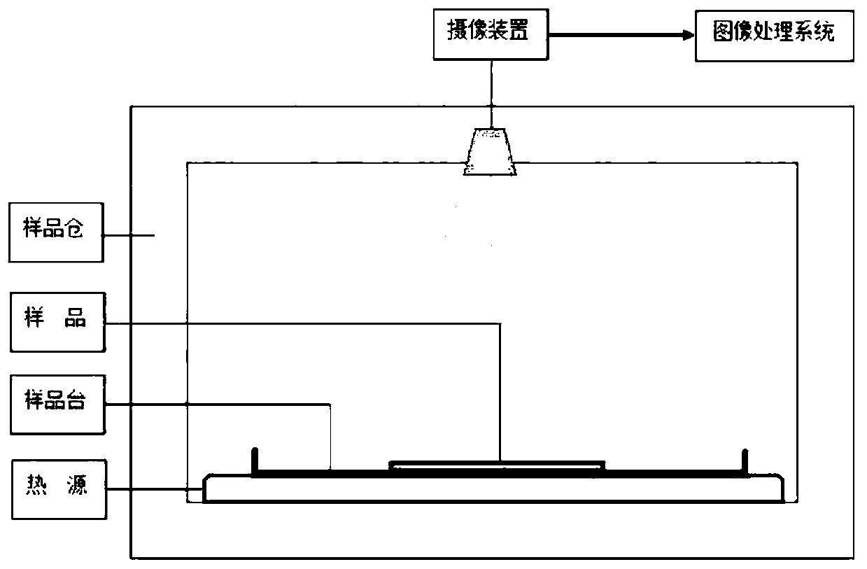
[0028] Take a diaphragm with a side length of 10cm*10cm, put it on a sample stage coated with a layer of talcum powder, and put it into an oven that has been kept at a constant temperature for 15 minutes at 30 degrees. For the image information of the sample, the initial area of ​​the sample is obtained through the image processing method. According to the set program, the method of programmed temperature rise is adopted, and the temperature rise rate is controlled to be 2 degrees per minute. After every 10 degrees rise, after staying for 10 minutes, the image information of the diaphragm is obtained through the camera device, and the area at different temperatures is obtained by image processing methods. The initial area is compared to obtain the shrinkage of the diaphragm.

Embodiment 2

[0029] Embodiment 2: Get a circular diaphragm with a diameter of 10 cm, put it on the sample platform coated with a layer of talcum powder on the surface, put it into an oven that has been kept at a constant temperature for 15 minutes at 40 degrees, and after the sample is placed for 15 minutes, pass through The imaging device obtains the image information of the sample, and obtains the initial area of ​​the sample through an image processing method. According to the set program, the method of programmed temperature rise is adopted, and the temperature rise rate is controlled at 2 degrees per minute. After every 10 degrees rise, after staying for 10 minutes, the image information of the diaphragm is obtained through the camera device, and the area under different temperatures is obtained by image processing method. The initial area is compared to obtain the shrinkage of the diaphragm.

Embodiment 3

[0030] Embodiment 3: Take a diaphragm of any shape, put it on the sample platform coated with a layer of talcum powder on the surface, put it into an oven that has been kept at a constant temperature for 15 minutes at 30 degrees, and after the sample is placed for 15 minutes, it will be obtained by a camera. The image information of the sample is processed by the area processing method to obtain the initial area of ​​the sample. According to the set program, the method of programmed temperature rise is adopted, and the temperature rise rate is controlled at 2 degrees per minute. After every 10 degrees rise, after staying for 10 minutes, the image information of the diaphragm is obtained through the camera device, and the area under different temperatures is obtained by image processing method. The initial area is compared to obtain the shrinkage of the diaphragm.


PUM


Abstract

The invention discloses a method for testing the thermal shrinkage rate of a battery diaphragm. According to the method, an image pickup device is adopted; the area change of the diaphragm at different temperatures is tested directly, so that the thermal shrinkage rate of the diaphragm is obtained. Equipment used in the method is simple; operation is convenient; and test precision is high. A wholetesting process can be continuously and automatically carried out, so that human influence factors are reduced; the area of the diaphragm is obtained through an image processing method. The thermal shrinkage rate of a diaphragm in any shape can be tested. The thermal shrinkage rate of the diaphragm at the different temperatures and the image information of the diaphragm at the different temperatures can be obtained more accurately.

Description

technical field [0001] The invention belongs to the technical field of energy materials, and in particular relates to a method for testing the heat shrinkage rate of a battery diaphragm. Background technique [0002] Secondary batteries are one of the hotspots in the field of energy research today. The diaphragm is an important component in the secondary battery. The main function in the secondary battery is to isolate the positive and negative electrodes of the battery to prevent the short circuit of the battery and provide a channel through which lithium ions can normally pass. [0003] During the use of the secondary battery, the overall temperature of the battery will rise due to the alternate charging and discharging process. In the process of temperature rise, the separator will shrink to different degrees and produce a certain shrinkage stress. When the shrinkage stress reaches a certain level, the separator will rupture, causing a short circuit of the battery and da...

Claims


Application Information

Patent Timeline
Patent Type & Authority Applications(China)
IPC IPC(8): G01N25/16G01B11/28
CPCG01B11/28G01N25/16
Inventor 田震赵敏王景伟
Owner SHANGHAI SECOND POLYTECHNIC UNIVERSITY
Why Eureka
Try Eureka