Edge grabbing method, edge grabbing system, machining equipment and machining system

A technology of processing equipment and processing system, which is applied in the field of edge grasping method, processing equipment and processing system, and edge grasping system, and can solve the problems that color distinction cannot realize automatic positioning, etc.

Active Publication Date: 2021-06-04
钧迪智能装备科技(苏州)有限公司
View PDF7 Cites 0 Cited by
  • Summary
  • Abstract
  • Description
  • Claims
  • Application Information

AI Technical Summary

Problems solved by technology

[0004] Therefore, the technical problem to be solved by the present invention is to overcome the defect that the glass cover plate in the prior art cannot realize automatic positioning except color distinction, thereby providing an edge grasping method, edge grasping system, processing equipment and processing system

Method used


Image

  • Edge grabbing method, edge grabbing system, machining equipment and machining system
  • Edge grabbing method, edge grabbing system, machining equipment and machining system
  • Edge grabbing method, edge grabbing system, machining equipment and machining system

Examples


Embodiment 1

[0046] This embodiment provides a method for grabbing edges, comprising the following steps:

[0047] S0: Obtain offset compensation parameters;

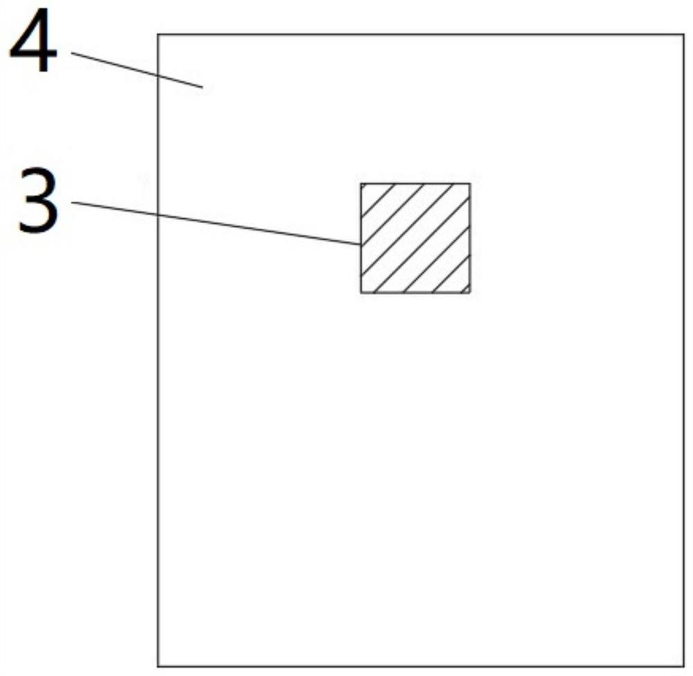
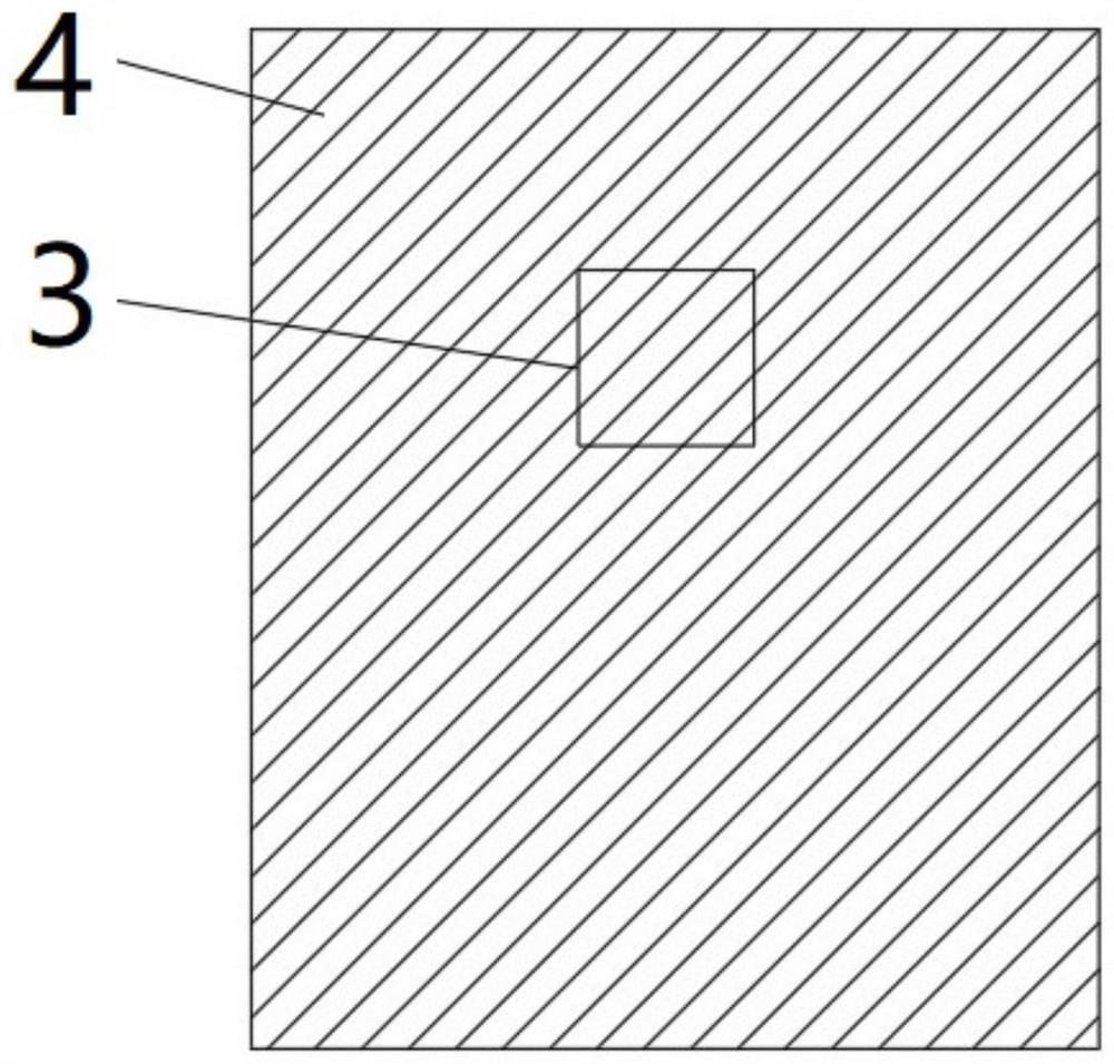
[0048] S1: placing the workpiece on the workbench 5, wherein the workpiece has an edge transition structure 31;

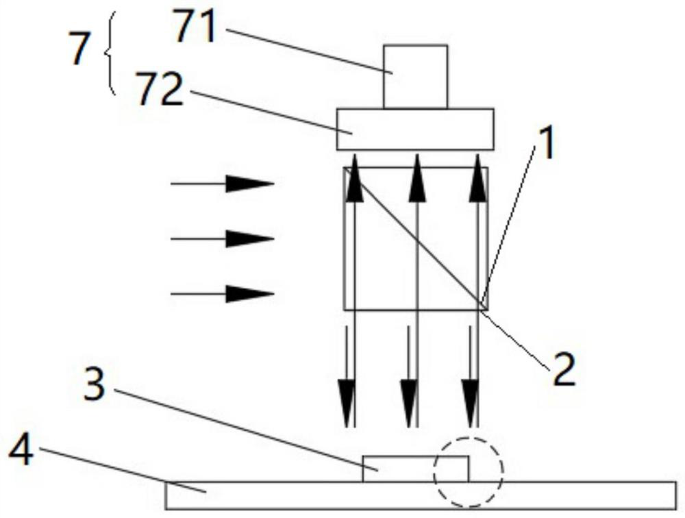
[0049] S2: The light source is irradiated vertically on the workpiece after being shaped by the light shaping unit;

[0050] S3: if image 3 , Figure 4 , Figure 6 to Figure 8 As shown, the light irradiated on the workpiece is reflected to the visual element 7 , the light contrast is obtained through the visual element 7 , and the position of the edge transition structure 31 is determined by the dark area of ​​the light contrast.

[0051] The light shaping part is a transparent lens 1, and the transparent lens 1 can be fixedly installed by the fixing part 2. Specifically, the reflective surface of the transparent lens 1 is set at an angle of 45 degrees, of course, the reflective surface of the transparent lens 1 ca...

Embodiment 2

[0060] This embodiment provides an edge grabbing system, including image 3 The workbench 5, the light shaping part and the visual part 7 are arranged in sequence from bottom to top, and the workpiece is grasped by the edge grasping method in the first embodiment. The visual component 7 may include a CCD 71 and an external lens 72 , or may not include the external lens 72 , or may be other visual components 7 .

Embodiment 3

[0062] This embodiment provides a processing device, including the edge gripping system in Embodiment 2. The processing equipment may be light processing equipment or other processing equipment. For details, see Figure 9 , the light processing equipment includes a stand 9, a base 6, a light processing device 8, and the edge gripping system in Embodiment 2, wherein the light processing device 8 is fixed on the stand 9, and the visual part 7 is fixed on the light processing device 8 Above, a workbench 5 is formed on the base 6 .

[0063] When the light processing equipment is working, the edge gripping system moves and grips the workpiece. Due to the limitation of the field of view of the edge-grabbing system, the edge-grabbing system can only obtain part of the edge of the first workpiece, and therefore only obtains the approximate position of the first workpiece. The edge gripping system is then moved along the vicinity of the edge of the first workpiece to determine the p...


PUM


Abstract

The invention discloses an edge grabbing method, an edge grabbing system, machining equipment and a machining system. The edge grabbing method comprises the following steps that S1, a workpiece is placed on a workbench, and the workpiece is provided with an edge transition structure; S2, a light source is shaped through a light shaping piece and then vertically irradiates the workpiece; and S3, the light irradiated on the workpiece is reflected to a visual part, light and shade contrast is obtained through the visual part, and the position of the edge transition structure is determined through a dark area of the light and shade contrast. In the process that light vertically irradiating the workpiece is reflected to the visual part, the light reflected by the edge transition structure is inclined, part of the reflected inclined light is captured by the visual part, the other part of the reflected inclined light is not captured by the visual part, and the light reflected by the upper wall face of the workpiece is vertical. The reflected vertical light can be captured by the visual part, light and shade contrast can be obtained through the visual part, and the position of the edge transition structure can be determined through the dark area so as to capture the edge of the workpiece.

Description

technical field [0001] The invention relates to the technical field of positioning, in particular to an edge grasping method, an edge grasping system, processing equipment and a processing system. Background technique [0002] The existing glass cover plate is first coated with photoresist in the spraying equipment before light treatment, wherein the photoresist is usually black or dark, and it is manually taken out after coating, and then the glass cover plate is placed on the stage. Among them, the carrier is usually transparent or white or bright, so when it will be as figure 1 When the glass cover with different color settings shown and the stage are placed together in the light processing equipment, the colors will have a sharp contrast, which is convenient for the CCD to grab the edge of the glass cover and then position the cover. CCD is a kind of visual device, which can capture obvious visual difference, and rely on the visual difference to obtain the edge of the o...

Claims


Application Information

Patent Timeline
Patent Type & Authority Applications(China)
IPC IPC(8): G03F7/20G03F7/16
CPCG03F7/20G03F7/70733G03F7/7085G03F7/16Y02P70/10
Inventor 张海滨徐维良陈亮吴景舟马迪
Owner 钧迪智能装备科技(苏州)有限公司
Why Eureka
Try Eureka