
State matrix-based optimal feedback control method applied to composite axis system

A technology of feedback control and state matrix, applied in the direction of adaptive control, general control system, control/regulation system, etc., can solve problems such as limited stability accuracy and system bandwidth limitation

Pending Publication Date: 2021-06-04
TIANJIN JINHANG INST OF TECH PHYSICS
View PDF11 Cites 4 Cited by
  • Summary
  • Abstract
  • Description
  • Claims
  • Application Information

AI Technical Summary

Problems solved by technology

[0002] Existing optoelectronic systems mostly use frame-type servo control platforms. Due to the existence of factors such as large moment of inertia, friction between shafts, and unbalanced moments, the bandwidth of the system is limited, resulting in limited stability and accuracy.

Method used


Image

  • State matrix-based optimal feedback control method applied to composite axis system
  • State matrix-based optimal feedback control method applied to composite axis system
  • State matrix-based optimal feedback control method applied to composite axis system

Examples


Embodiment Construction

[0033] In order to make the purpose, content, and advantages of the present invention clearer, the specific implementation manners of the present invention will be further described in detail below in conjunction with the accompanying drawings and embodiments.

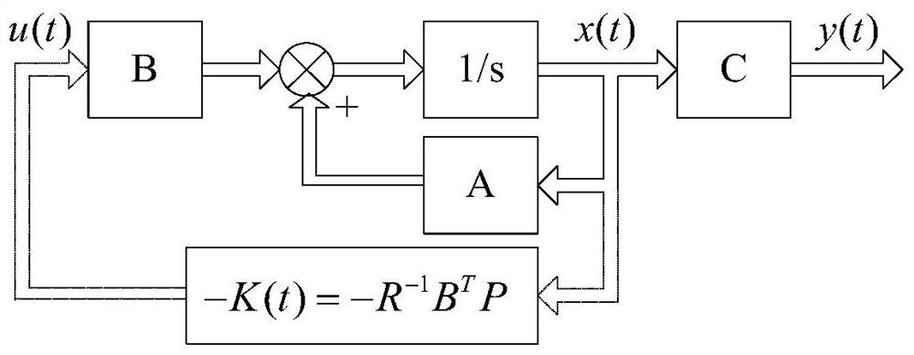
[0034] The invention designs a control method for improving the stability precision, which is realized by modeling the state space of the controlled object, analyzing the state quantity of the control system and designing the optimal state feedback based on the state matrix. Specifically include the following steps:

[0035] (1) Establish a state space model for the controlled object of the system, including:

[0036] A fast mirror assembly driven by a piezoelectric ceramic is taken as an example for illustration. The fast mirror assembly model G(s) consists of four parts, G 1 (s) is the drive module transfer function, G 2 (s) is the electrical transfer function of piezoelectric ceramics, G 3 (s) is the piezoelectr...


PUM


Abstract

The invention relates to a state matrix-based optimal feedback control method applied to a composite axis system, which comprises the following steps of: establishing a state space model for a controlled object of the system; analyzing the state quantity of the control system; designing optimal state feedback based on the state matrix; carrying out optimal feedback control design on the basis of a state space model and each state quantity of a known controlled object, and establishing an optimal control performance index for a control system based on a state space matrix; adjusting the state quantity x and the control quantity u of the system comprehensively, so that the performance index J of the system obtains the minimum value; setting a parameter matrix, and then solving and deducing a state feedback matrix of the control system; and performing optimal feedback control according to each state quantity gain in the state feedback matrix. According to the invention, the precision of the fast reflector control system can be greatly improved.

Description

technical field [0001] The invention relates to an optimal control method of a photoelectric composite shaft system, in particular to an optimal feedback control method based on a state matrix of a photoelectric composite shaft system. Background technique [0002] Existing optoelectronic systems mostly use frame-type servo control platforms. Due to the existence of factors such as large moment of inertia, friction between shafts, and unbalanced moments, the bandwidth of the system is limited, resulting in limited stability and accuracy. The composite axis control technology adds a fast mirror component that can deflect quickly according to the command to the existing frame platform, and uses the fast mirror to fine-stabilize the error of the coarse stability of the frame platform control system, thus forming a coarse-fine dual level stable control system. Due to the relatively high rigidity of the fast mirror assembly and relatively accurate model building, the closed-loop...

Claims


Application Information

Patent Timeline
IPC IPC(8): G05B13/04
CPCG05B13/042
Inventor 戴川孙拓
Owner TIANJIN JINHANG INST OF TECH PHYSICS
Learn More