A Method of Visual Feature Extraction for Aerospace Composite Material Damage

A composite material and feature extraction technology, applied in the field of aerospace composite material damage visualization feature extraction, can solve problems such as defect recognition misjudgment, unfavorable image segmentation, reduce defect detection rate and detection accuracy, and achieve strong applicability

Active Publication Date: 2022-03-04
中国空气动力研究与发展中心超高速空气动力研究所
View PDF5 Cites 0 Cited by
  • Summary
  • Abstract
  • Description
  • Claims
  • Application Information

AI Technical Summary

Problems solved by technology

On the one hand, if the defect detection rate is improved to a certain extent under the premise of fully satisfying the preservation of details, the noise is also retained, which is easy to cause misjudgment of defect recognition, resulting in an increase in the false detection rate
On the other hand, if only the overall denoising of the image is satisfied, the size of the damage defects caused by the impact of tiny debris is small and the number is large, and these tiny defects similar to the noise will be removed together with the denoising process, reducing the damage of defects. Detection rate and detection accuracy
Therefore, the above-mentioned conventional segmentation method is applied to the object of the present invention, that is, the infrared reconstructed image of the defect. Since the false detection rate and detection rate of the defect cannot be weighed, the segmentation effect is not satisfactory.
Especially considering that the infrared thermal image reflects the thermal radiation information of the test piece, which is easily affected by the environment, imaging links, etc., so that the background noise of the obtained infrared reconstruction image of defects is large.
At the same time, due to the difference in surface thermal radiation capabilities between the defect area and the background area, the edges of the infrared reconstructed image of the defect are not smooth enough, and the division of edge areas is not clear enough, which is not conducive to image segmentation

Method used


Image

  • A Method of Visual Feature Extraction for Aerospace Composite Material Damage
  • A Method of Visual Feature Extraction for Aerospace Composite Material Damage
  • A Method of Visual Feature Extraction for Aerospace Composite Material Damage

Examples


Embodiment

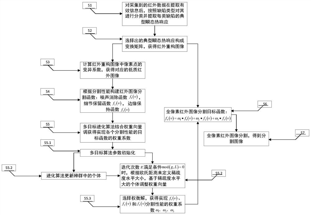
[0220] In this embodiment, the infrared thermal imager collected 363 frames of images with a pixel size of 512×640. That is, there are 327,680 temperature points on each map, and the temperature value of each temperature point is recorded 363 times. This time-varying temperature condition constitutes the transient thermal response TTR of the temperature point. Step 1: After extracting the effective transient thermal response from the infrared thermal sequence, divide the area according to the defect type, and extract the typical transient thermal response from each type of divided area. When extracting the effective transient thermal response, set the parameter Re CL =0.92, 375 valid transient thermal responses containing complete defect information were extracted from 327,680 temperature points. According to the pixel points, the membership degree of each cluster center is softened, and 121, 108 and 146 thermal response curves are divided into corresponding categories. Ex...


PUM


Abstract

The invention discloses a damage visualization feature extraction method for aerospace composite materials, comprising: extracting the typical transient thermal response of each type of defect; obtaining an infrared reconstruction image; obtaining a low-quality infrared reconstruction image; calculating the weight of each segmentation performance Coefficient to build segmentation objective function; obtain the weight coefficient of the objective function of each segmentation performance; construct the full pixel infrared image segmentation objective function, use the double-layer segmentation model to perform image segmentation on the reconstructed full pixel infrared image; realize in the image segmentation layer Infrared full-pixel image segmentation to obtain segmented images of specimen defects. The invention utilizes multi-objective optimization theory to segment defects in infrared reconstructed images, constructs objective functions for noise and edge blur problems to improve the accuracy of segmentation, ensures a high detection rate of defects, reduces false detection rates, and effectively extracts The damage defect area in the reconstructed image is extracted for the quantitative study of complex defects.

Description

technical field [0001] The invention belongs to the technical field of aerospace vehicle damage detection and maintenance support, and more specifically, the invention relates to a method for extracting visual feature of damage of aerospace composite materials. Background technique [0002] With the urgent need for weight reduction of aerospace vehicles, lightweight structural materials with excellent mechanical properties, especially lightweight composite materials represented by high-strength / high-modulus carbon fiber composite materials and honeycomb structure materials, have increasingly become the focus of aerospace research. hotspot. At the same time, composite materials with special functional uses, such as stealth coating materials, carbon-based heat-resistant materials and other functional composite materials, are also more widely used in the aerospace field. However, in the process of manufacturing, assembly processing or real-time use of composite materials, seri...

Claims


Application Information

Patent Timeline
Patent Type & Authority Patents(China)
IPC IPC(8): G06V10/56G06V10/26G06V10/44G06V10/74G06V10/764G06V10/762G06K9/62G06T7/00G06T5/00G06N3/12
CPCG06T5/002G06T7/0004G06N3/126G06T2207/30108G06T2207/20192G06T2207/10048G06V10/267G06V10/56G06V10/44G06F18/23G06F18/22G06F18/24
Inventor 黄雪刚雷光钰殷春谭旭彤罗庆石安华覃金贵
Owner 中国空气动力研究与发展中心超高速空气动力研究所
Why Eureka
Try Eureka