
Stator bar transposition method for formed transposition winding permanent magnet synchronous motor

A permanent magnet synchronous motor and stator bar technology, applied in the direction of the shape/style/structure of the winding conductor, can solve the problems of the decrease of the circulation suppression effect, the decrease of the space occupied by the slot, and the decrease of the motor slot full rate, so as to reduce the The effect of heat generation, increasing tank full rate, and reducing circulation loss

Active Publication Date: 2021-06-04
HARBIN UNIV OF SCI & TECH
View PDF6 Cites 3 Cited by
  • Summary
  • Abstract
  • Description
  • Claims
  • Application Information

AI Technical Summary

Problems solved by technology

[0004] The present invention aims to solve the problem that after the traditional intra-turn transposition is applied to a permanent magnet synchronous motor with more coil turns per slot, the transposition of each coil turns requires more space for transposition. Occupying the space in the slot is reduced, which in turn causes the problem of the decrease of the motor slot full rate and the decrease of the circulation suppression effect. Now a method for transposition of the stator bar of the permanent magnet synchronous motor with formed transposition winding is provided.

Method used


Image

  • Stator bar transposition method for formed transposition winding permanent magnet synchronous motor
  • Stator bar transposition method for formed transposition winding permanent magnet synchronous motor
  • Stator bar transposition method for formed transposition winding permanent magnet synchronous motor

Examples


specific Embodiment approach 1

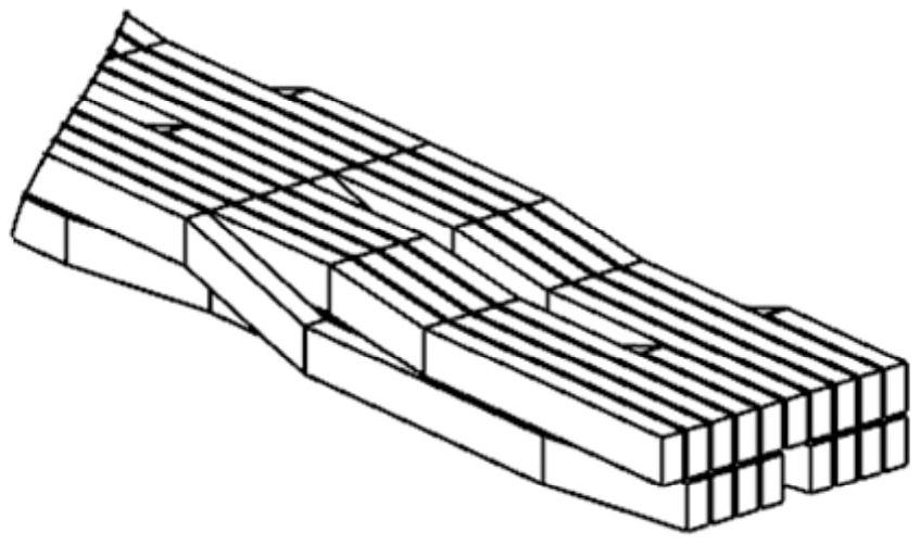
[0028] Specific implementation mode one: refer to figure 2 , 4 , 6, 7 and 9 specifically illustrate this embodiment, a method for transpositioning a stator bar of a permanent magnet synchronous motor with a forming transposition winding described in this embodiment, wherein the permanent magnet synchronous motor includes M layers of windings, and each layer of windings includes N turn coil, the strands in the coil are all flat wire structures. In this embodiment, N=2, and all strands in the 2-turn coil are regarded as a whole, that is, a group. The strands are arranged in 2 rows with 9 and 10 strands respectively, so that only one strand vacancy occurs in the two half-turn coils. Therefore, during the transposition, the 19 strands are transposed together by interweaving 360° between turns. The two coils overlap in the radial space of the slot, and each strand passes through the entire inner space during the transposition process. .

[0029] Specifically:

[0030] The str...


PUM


Abstract

The invention discloses a stator bar transposition method for a formed transposition winding permanent magnet synchronous motor, and relates to the technical field of permanent magnet synchronous motor design and manufacturing. The invention aims to solve the problems that after the traditional in-turn transposition is applied to the permanent magnet synchronous motor with more turns of coils in each slot, the required transposition space is more due to respective transposition of the coils in each turn, and the space occupied by each strand in the slot is reduced during transposition, so that the slot fullness rate of the motor and the circulating current suppression effect are reduced. According to the stator bar transposition method of the formed transposition winding permanent magnet synchronous motor, the permanent magnet synchronous motor comprises one or two layers of windings, each layer of winding comprises N turns of coils, all strands in the N turns of coils are divided into K groups, the strands in each group are arranged into two rows, the strands are of flat wire structures, and all strands in each group are subjected to transposition in a turn-to-turn interweaving transposition mode. The method is not only suitable for horizontal transposition, but also suitable for Roebel bar transposition.

Description

technical field [0001] The invention belongs to the technical field of permanent magnet synchronous motor design and manufacture. Background technique [0002] As permanent magnet synchronous motors are more and more widely used in the field of new energy vehicles, further improving the efficiency and operating performance of motors has become the focus of permanent magnet synchronous motor research and development at this stage. Since the flat wire structure winding can improve the motor slot full rate, the hairpin winding with the flat wire structure is more and more applied to the permanent magnet synchronous motor for vehicle drive. However, there are certain problems in flat wire motors at this stage. For example, the additional current in the motor winding includes two types of eddy current and circulating current. After the wire diameter increases, both currents will increase. The flat wire structure can suppress the eddy current but cannot suppress the circulating cu...

Claims


Application Information

Patent Timeline
Patent Type & Authority Applications(China)
IPC IPC(8): H02K3/28H02K3/14H02K3/04
CPCH02K3/04H02K3/14H02K3/28
Inventor 梁艳萍赵富超汪冬梅王伟豪徐康文
Owner HARBIN UNIV OF SCI & TECH
Learn More