Building steel bar rust removal device capable of reducing surface abrasion

A surface wear, construction technology, used in grinding/polishing safety devices, grinding machines, grinding/polishing equipment, etc., can solve problems such as reduced flatness, easy rust on side walls, and difficulty in grasping concrete fusion.

Inactive Publication Date: 2021-06-08
黄千源
View PDF0 Cites 0 Cited by
  • Summary
  • Abstract
  • Description
  • Claims
  • Application Information

AI Technical Summary

Problems solved by technology

[0002] When building a foundation, in order to ensure stability, steel bars will be interspersed with each other. Concrete and steel bars can be mixed together, which can play a role in tensile stress on the cohesion of concrete and enhance a certain degree of tensile strength. Strength, after the height of the house increases, the steel bar can also add a certain degree of compressive effect to the house, etc. During the transportation of the steel bar, due to various reasons such as weather, a humid environment will be created for the side wall of the steel bar. As a result, the side wall of the steel bar is prone to rust, reducing the flatness, and the space between the lines on the side wall of the steel bar will be filled with rust, making it difficult to grasp the concrete for better integration when it is used again

Method used


Image

  • Building steel bar rust removal device capable of reducing surface abrasion
  • Building steel bar rust removal device capable of reducing surface abrasion
  • Building steel bar rust removal device capable of reducing surface abrasion

Examples


Embodiment Construction

[0020] The following will clearly and completely describe the technical solutions in the embodiments of the present invention with reference to the accompanying drawings in the embodiments of the present invention. Obviously, the described embodiments are only some, not all, embodiments of the present invention. Based on the embodiments of the present invention, all other embodiments obtained by persons of ordinary skill in the art without making creative efforts belong to the protection scope of the present invention.

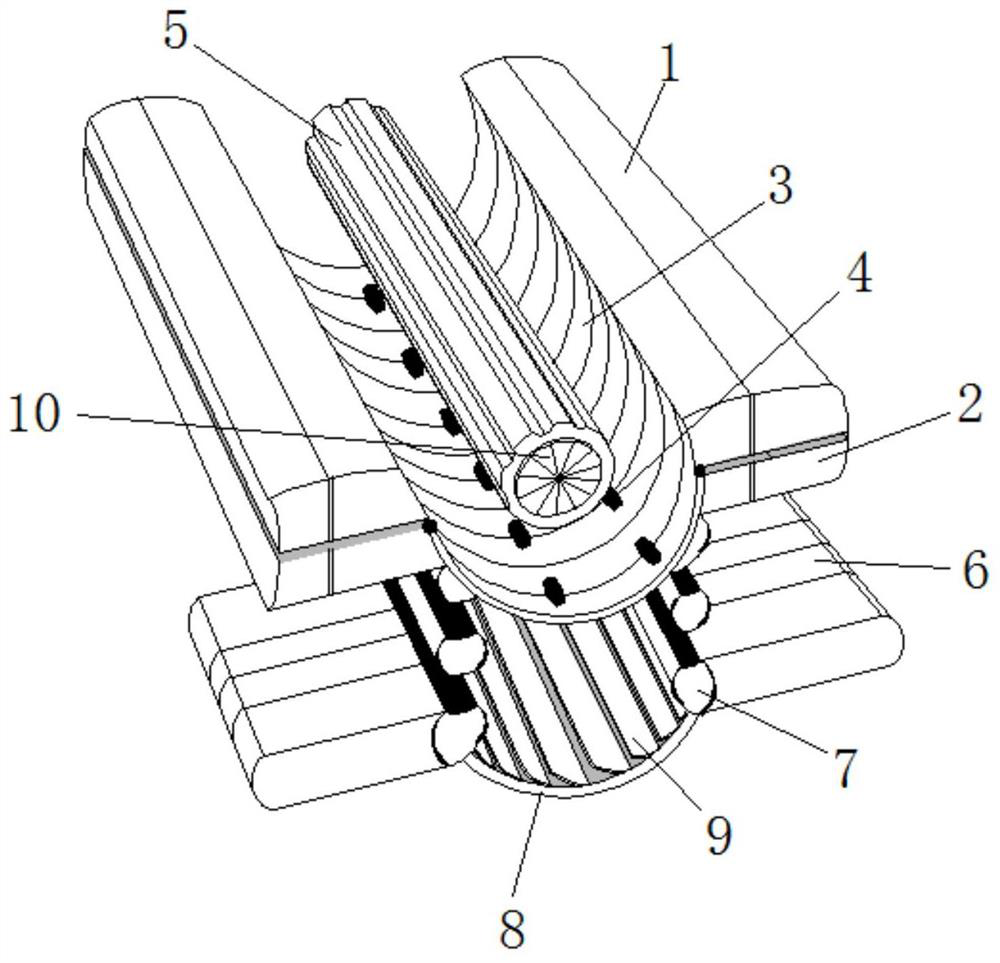
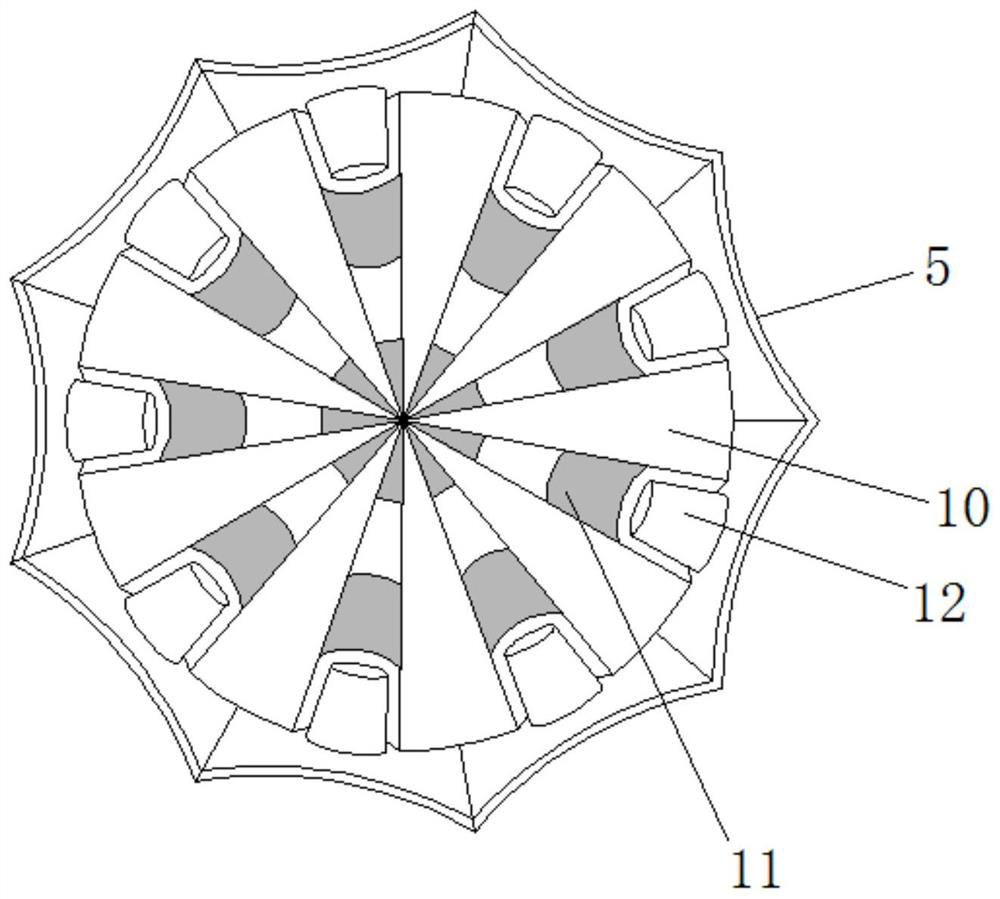
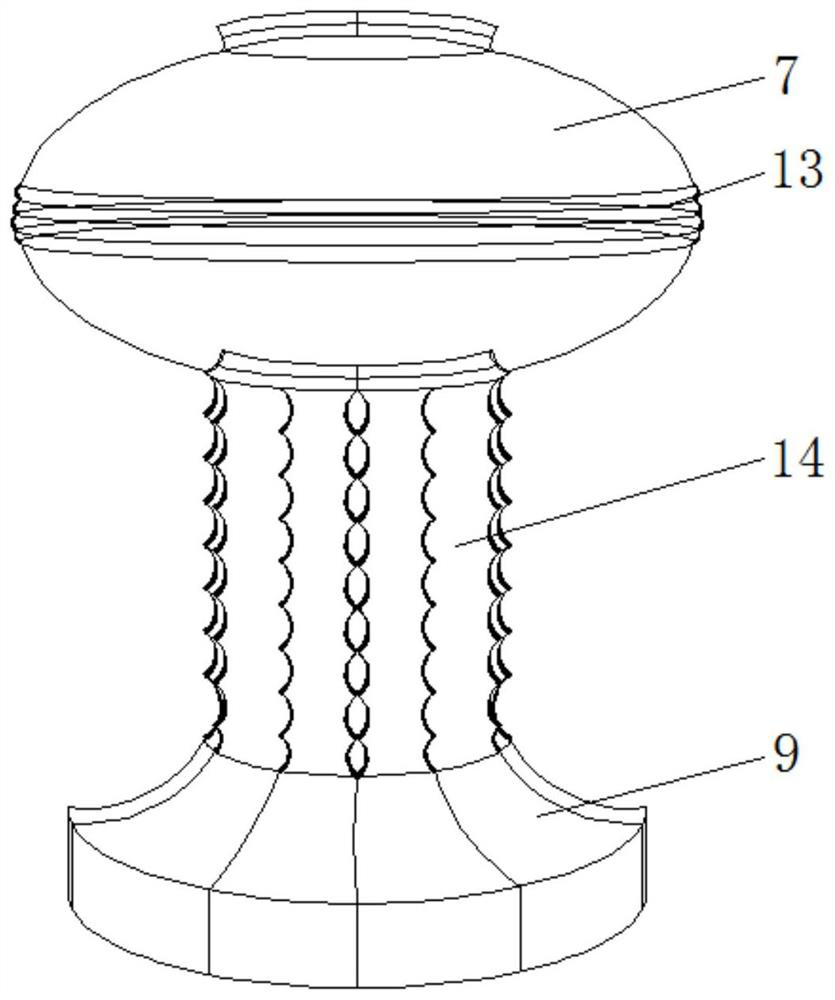
[0021] see Figure 1-3 , a kind of derusting device for building steel bars that reduces surface wear, comprising a movable column 1, a movable block 3 runs through the side wall of the movable column 1, a connecting block 4 runs through the top side wall of the movable block 3, and the movable block 3 A movable shaft 10 runs through the top side wall of the movable shaft 10, and a movable bar 5 runs through and is slidably connected to the outer wall of the m...


PUM


Abstract

The invention relates to the technical field of steel bar rust removal equipment, and discloses a building steel bar rust removal device capable of reducing surface abrasion. The building steel bar rust removal device capable of reducing surface abrasion comprises a movable column; a movable block penetrates through the side wall of the movable column; a connecting block penetrates through the top side wall of the movable block; a movable shaft penetrates through the top side wall of the movable block; and a movable strip penetrates through and is slidably connected to the outer side wall of the movable shaft, and a sliding piece is connected between the side walls of the movable shaft in a penetrating mode. Due to the fact that the side wall of the movable strip wraps the outer side wall of the movable shaft, in the process that the side wall of a steel bar pipe slides downwards along the inner side wall of the movable block, the side wall of the steel bar pipe can be scraped on the outer side wall of the movable strip, and the side wall of the movable strip rotates and slides on the side wall of the movable shaft, as can be seen from the drawing; when the side wall of the movable strip rotates and twists, the sharp corner of the side wall of the movable strip protrudes outwards; and due to the fact that the side wall of a steel bar rod can be scraped right opposite to the sharp corner of the outer side wall of the movable strip, rust at a gap of the side wall of the steel bar rod can be scraped and removed.

Description

technical field [0001] The invention relates to the technical field of steel bar derusting equipment, in particular to a construction steel bar derusting device which reduces surface wear. Background technique [0002] When building a foundation, in order to ensure stability, steel bars will be interspersed with each other. Concrete and steel bars can be mixed together, which can play a role in tensile stress on the cohesion of concrete and enhance a certain degree of tensile strength. Strength, after the height of the house increases, the steel bar can also add a certain degree of compressive effect to the house, etc. During the transportation of the steel bar, due to various reasons such as weather, a humid environment will be created for the side wall of the steel bar. As a result, the side wall of the steel bar is prone to rust, which reduces the flatness, and the space between the lines on the side wall of the steel bar will be filled with rust, making it difficult to g...

Claims


Application Information

Patent Timeline
Patent Type & Authority Applications(China)
IPC IPC(8): B24B27/033B24B55/06B08B1/00B08B5/02
CPCB08B1/005B08B5/02B24B27/033B24B55/06
Inventor 黄千源
Owner 黄千源
Why Eureka
Try Eureka