Aero-engine rim sealing structure

A technology of aero-engines and rims, which is applied in the direction of engine components, machines/engines, mechanical equipment, etc., and can solve problems such as small sealing resistance, reduced engine efficiency, and reduced turbine efficiency

Inactive Publication Date: 2021-06-08
AECC SHENYANG ENGINE RES INST
View PDF5 Cites 2 Cited by
  • Summary
  • Abstract
  • Description
  • Claims
  • Application Information

AI Technical Summary

Problems solved by technology

[0004] However, the current sealing structure of the turbine rim still has a small sealing resistance, resulting in a large flow of sealed cold air, which in turn reduces the efficiency of the turbine
In addition, the cold air used to prevent gas intrusion is directly blown into the main channel of the turbine radially, and mixed with the gas flowing in the axial direction, resulting in obvious mixing loss, reducing the work efficiency of the gas, and reducing the efficiency of the turbine
This leads to reduced engine efficiency and increased fuel consumption

Method used


Image

  • Aero-engine rim sealing structure
  • Aero-engine rim sealing structure
  • Aero-engine rim sealing structure

Examples


Embodiment Construction

[0031] In order to make the purpose, technical solution and advantages of the application more clear, the technical solution in the embodiment of the application will be described in more detail below in conjunction with the drawings in the embodiment of the application.

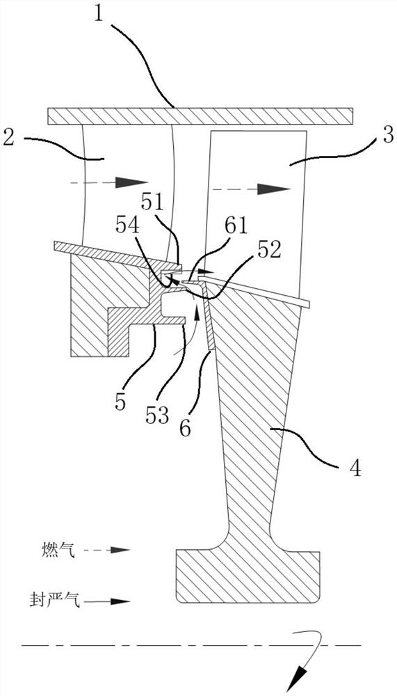
[0032] In order to effectively improve the sealing effect of the wheel flange, reduce the mixing loss of gas and cold air, make the cooling air work on the turbine, improve the efficiency of the turbine, and reduce the fuel consumption of the engine, this application provides a wheel with a circumferential flow guide function. Edge sealing structure.

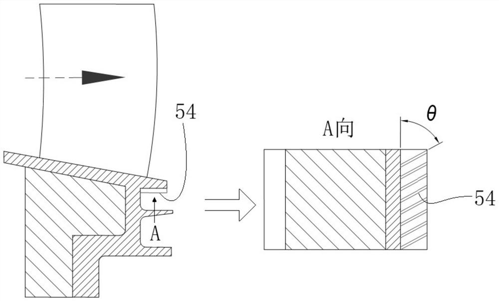
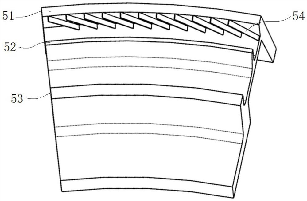
[0033] Such as Figure 1 to Figure 4 As shown, the aeroengine rim sealing structure specifically provided by the present application includes: guide vanes 2, rotor blades 3, and the rim sealing front structure 5 installed on the guide vanes 2 and the rim sealing structure installed on the rotor blades 3. The rear structure 6 and the front structure 5 of the w...


PUM


Abstract

The invention provides an aero-engine rim sealing structure. The aero-engine rim sealing structure comprises: a guide blade; a rotor blade; and a front rim sealing structure installed on the guide blade and a rear rim sealing structure installed on the rotor blade, wherein the front rim sealing structure is provided with a first backward protrusion and a second backward protrusion which extend in the direction of a main airflow runner, the first backward protrusion and the second backward protrusion form a first groove, a flow deflector is arranged on the upper wall of the first groove, the rear rim sealing structure is provided with a first forward protrusion extending in the direction opposite to the direction of the main airflow channel, and at least part of the first forward protrusion extends into the first groove. On one hand, the flow resistance of hot fuel gas flowing to a gap can be increased in the operation process of the engine, so that the sealing effect is improved, on the other hand, the mixing loss of the fuel gas and cold air can be reduced, the cold air acts on a turbine, the acting efficiency of the fuel gas is improved, the turbine efficiency is improved, and the oil consumption rate of the engine is reduced.

Description

technical field [0001] The application belongs to the technical field of aero-engines, in particular to an aero-engine rim sealing structure. Background technique [0002] During the working process of an aero-engine, the high-temperature gas in the main channel of the turbine will enter the turbine disc cavity from the gap between the turbine rotor and the stator. This phenomenon is called gas intrusion. Gas intrusion will increase the temperature of the disk cavity, which will cause the temperature of the turbine disk to overheat and the temperature of the bearing cavity to be too high, which will bring safety hazards to the engine and affect the service life of the engine. [0003] In order to prevent gas intrusion, cold air is usually provided to the turbine disc cavity and discharged into the main flow channel through the gap between the turbine rotor and the stator. On this basis, a flange sealing structure is usually set on the outer diameter of the turbine disk to i...

Claims


Application Information

Patent Timeline
Patent Type & Authority Applications(China)
IPC IPC(8): F01D11/00F01D25/00F01D25/12
CPCF01D11/003F01D25/00F01D25/12
Inventor 王家友段玉发范宇邓明春周建军
Owner AECC SHENYANG ENGINE RES INST
Why Eureka
Try Eureka