Acceleration measuring device based on single-path optical fiber

A technology of acceleration measurement and optical fiber, which is applied in the direction of measuring device, velocity/acceleration/shock measurement, acceleration measurement using inertial force, etc., which can solve the problems of low measurement sensitivity and inaccurate measurement

Inactive Publication Date: 2021-06-08
王计兰
View PDF0 Cites 0 Cited by
  • Summary
  • Abstract
  • Description
  • Claims
  • Application Information

AI Technical Summary

Problems solved by technology

[0004] The object of the present invention is to provide an acceleration measurement device based on a single-channel optical fiber, which solves the problems of low measurement sensitivity and inaccurate measurement

Method used


Image

  • Acceleration measuring device based on single-path optical fiber
  • Acceleration measuring device based on single-path optical fiber
  • Acceleration measuring device based on single-path optical fiber

Examples


Embodiment 1

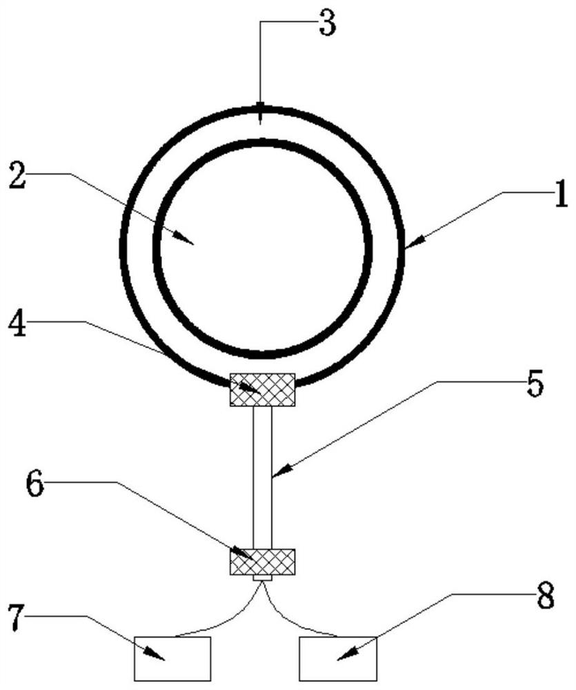
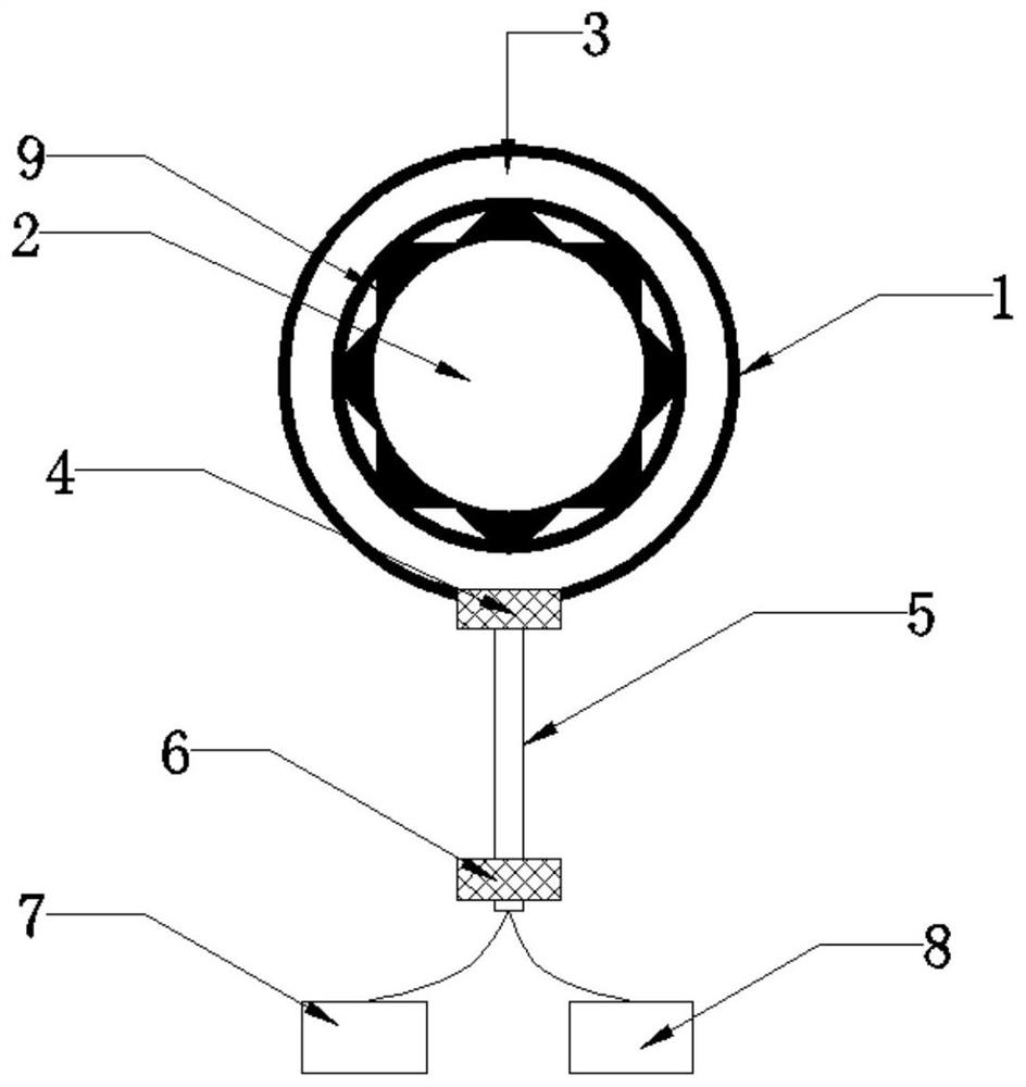
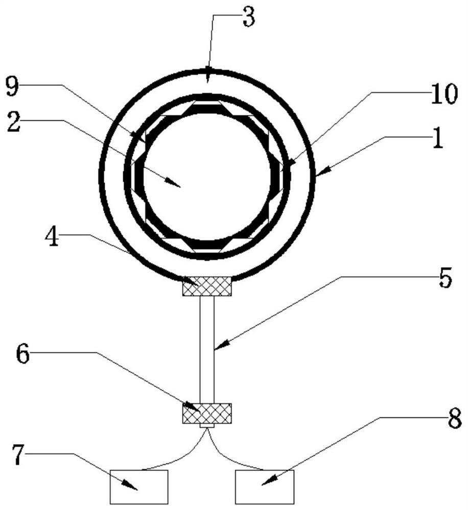
[0021] see figure 1 , an acceleration measurement device based on a single-channel optical fiber, comprising a cylindrical airtight container 1, a cylindrical steel block 2 is arranged at the center of the cylindrical airtight container 1, and a protrusion is arranged at the side end of the cylindrical steel block 2 9. The protrusion 9 is provided with an elastic material 10, the column wall of the cylindrical airtight container 1 is provided with an optical fiber 3, and the front position of the column side end of the cylindrical airtight container 1 is provided with an optical fiber inlet 4, and the optical fiber inlet 4 is connected with an input optical fiber 5 The end of the input optical fiber 5 away from the fiber entrance 4 is provided with a bidirectional coupler 6, and the two ends of the bottom of the bidirectional coupler 6 are provided with a light source 7 and a photodetector 8. The ends are symmetrically distributed, and the light source 7 and the photodetector ...

Embodiment 2

[0024] see figure 1 , an acceleration measurement device based on a single-channel optical fiber, comprising a cylindrical airtight container 1, a cylindrical steel block 2 is arranged at the center of the cylindrical airtight container 1, and a protrusion is arranged at the side end of the cylindrical steel block 2 9. The protrusion 9 is provided with an elastic material 10, the column wall of the cylindrical airtight container 1 is provided with an optical fiber 3, and the front position of the column side end of the cylindrical airtight container 1 is provided with an optical fiber inlet 4, and the optical fiber inlet 4 is connected with an input optical fiber 5 The end of the input optical fiber 5 away from the fiber entrance 4 is provided with a bidirectional coupler 6, and the two ends of the bottom of the bidirectional coupler 6 are provided with a light source 7 and a photodetector 8. The ends are symmetrically distributed, and the light source 7 and the photodetector ...

Embodiment 3

[0028] see figure 1 , an acceleration measurement device based on a single-channel optical fiber, comprising a cylindrical airtight container 1, a cylindrical steel block 2 is arranged at the center of the cylindrical airtight container 1, and a protrusion is arranged at the side end of the cylindrical steel block 2 9. The protrusion 9 is provided with an elastic material 10, the column wall of the cylindrical airtight container 1 is provided with an optical fiber 3, and the front position of the column side end of the cylindrical airtight container 1 is provided with an optical fiber inlet 4, and the optical fiber inlet 4 is connected with an input optical fiber 5 The end of the input optical fiber 5 away from the fiber entrance 4 is provided with a bidirectional coupler 6, and the two ends of the bottom of the bidirectional coupler 6 are provided with a light source 7 and a photodetector 8. The ends are symmetrically distributed, and the light source 7 and the photodetector ...


PUM


Abstract

The invention belongs to the technical field of acceleration measuring devices, and particularly relates to an acceleration measuring device based on a single-path optical fiber. The device comprises a cylindrical closed container, a cylindrical steel block is arranged at the column center position of the cylindrical closed container, a bulge is arranged at the column side end of the cylindrical steel block, and an elastic material is arranged in the bulge. An optical fiber is arranged on the column wall of the cylindrical closed container, an optical fiber inlet is formed in the front face of the column side end of the cylindrical closed container and connected with an input optical fiber, and a bidirectional coupler is arranged at the end, away from the optical fiber inlet, of the input optical fiber. A light source and a light detector are arranged at the two ends of the bottom of the bidirectional coupler. The acceleration in the horizontal direction is reflected by measuring the changing light, and due to the fact that the change of the light is sensitive, the design has high precision and high sensitivity.

Description

technical field [0001] The invention relates to the technical field of acceleration measuring devices, in particular to an acceleration measuring device based on a single optical fiber. Background technique [0002] An instrument for measuring the linear acceleration and vibration parameters of a moving object, which consists of an acceleration sensor and an amplifier. In order to amplify the small output signal of the piezoelectric acceleration sensor, the sensor can be used in conjunction with a voltage amplifier or a charge amplifier. Piezoelectric acceleration sensor has high natural frequency, small size, light weight and high sensitivity. But its low frequency performance is poor, the output signal is small and the output impedance is high. In addition, there are strain-type and differential transformer-type acceleration sensors. [0003] In the prior art, due to the limitation of the traditional structure, the sensitivity to acceleration measurement is low, and the...

Claims


Application Information

Patent Timeline
IPC IPC(8): G01P15/00G01P15/03
CPCG01P15/00G01P15/032
Inventor 不公告发明人
Owner 王计兰
Why Eureka
Try Eureka