
Laser light field visualization device and method based on InGaAs camera

A laser and camera technology, applied in the field of photoelectric countermeasures system, can solve problems and solve problems that have not been explained, and achieve the effect of high angle resolution accuracy

Active Publication Date: 2021-06-08
ARMY ENG UNIV OF PLA
View PDF11 Cites 0 Cited by
  • Summary
  • Abstract
  • Description
  • Claims
  • Application Information

AI Technical Summary

Problems solved by technology

This problem and solution are not explained in this patent

Method used


Image

  • Laser light field visualization device and method based on InGaAs camera
  • Laser light field visualization device and method based on InGaAs camera

Examples


Embodiment Construction

[0031] In order to facilitate those skilled in the art to understand and implement the present invention, the present invention will be described in further detail below. It should be understood that the content described here is only for illustrating and explaining the present invention, and is not intended to limit the present invention.

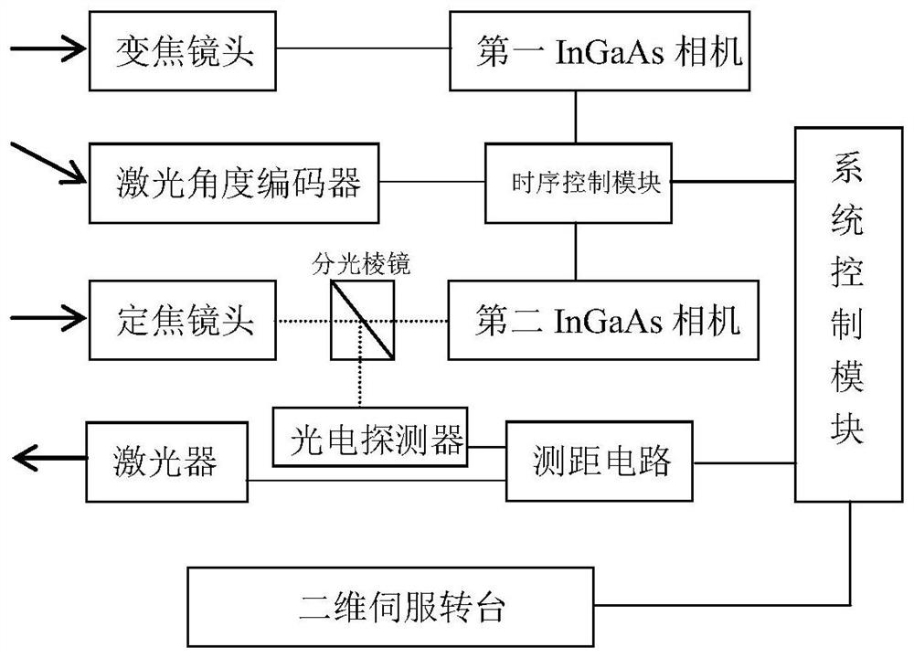
[0032] like figure 1 As shown, a laser light field visualization device based on an InGaAs camera includes a two-dimensional servo turntable, a zoom lens set on the two-dimensional servo turntable, a fixed-focus lens, a first InGaAs camera, a second InGaAs camera, and a laser angle encoder. Devices, timing control modules, lasers, photodetectors, ranging circuits, beam splitters, and system control modules.

[0033] The laser angle encoder responds to the incident light of the set band, and encodes the angle of the incident light, and outputs the laser incident angle and laser incident time to the timing control module.

[0034] The targe...


PUM


Abstract

The invention discloses a laser light field visualization device based on an InGaAs camera, and the device comprises a two-dimensional servo turntable. The device further comprises a zoom lens, a prime lens, a first InGaAs camera, a second InGaAs camera, a laser angle encoder, a sequential control module, a laser, a photoelectric detector, a distance measuring circuit, a beam splitter prism and a system control module which are arranged on the two-dimensional servo turntable. The invention further discloses a laser light field visualization method based on the InGaAs cameras. Capturing and imaging of laser at an unknown emission moment are realized, and light field visualization is realized. The problem of capturing and imaging of laser beams at unknown emission moments is solved, the angle positioning resolution is high, and the visualization of a laser light field is realized.

Description

technical field [0001] The present invention relates to the field of optoelectronic countermeasure systems, more specifically to a laser light field visualization device based on an InGaAs camera, and also to a laser light field visualization method based on an InGaAs camera, which can realize the capture and imaging of laser light at unknown emission times, Realize visualization. Background technique [0002] The capture imaging of laser light field is an important content of laser warning technology and an important part of photoelectric countermeasures. On the battlefield, whoever discovers the opponent first will have the upper hand and take the initiative. Only by accurately obtaining the characteristics and orientation of the incoming laser, can we take correct defensive measures accordingly and protect our own safety at the first time. On this basis, according to the exact location of the threat source, effective countermeasures can be taken to interfere or destroy ...

Claims


Application Information

Patent Timeline
Patent Type & Authority Applications(China)
IPC IPC(8): G01S17/89G01S17/08G01S7/495
CPCG01S17/89G01S17/08G01S7/495
Inventor 曹海源黎伟陆益敏初华黄国俊米朝伟朱孟真韦尚方
Owner ARMY ENG UNIV OF PLA
Learn More