
STI forming method

A technology of wet etching and shallow trenches, which is applied in the direction of radiation control devices, semiconductor devices, electrical components, etc., can solve the problems of over-etching of the lining silicon nitride layer, achieve the effect of improving device performance and avoiding pit defects

Inactive Publication Date: 2021-06-08
HUA HONG SEMICON WUXI LTD
View PDF4 Cites 0 Cited by
  • Summary
  • Abstract
  • Description
  • Claims
  • Application Information

AI Technical Summary

Problems solved by technology

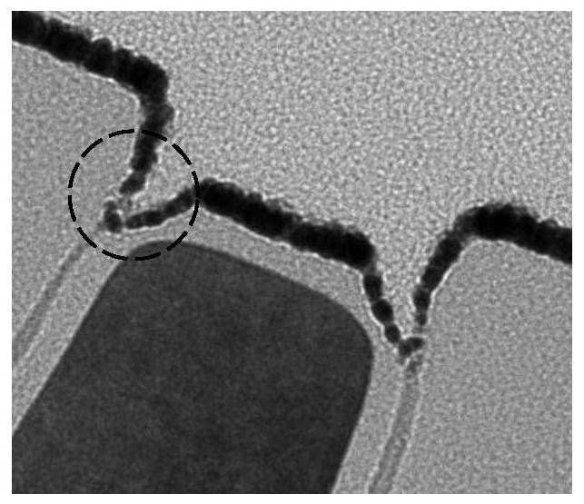
[0004] However, when the substrate is etched to form a trench, a pad silicon nitride layer is formed on the surface of the substrate. The difference in etch rate of the silicon nitride layer will lead to over-etching of the lining silicon nitride layer, and a depression (divot) will be generated at the top corner of the shallow trench isolation, such as figure 1 shown

Method used


Image

  • STI forming method
  • STI forming method
  • STI forming method

Examples


Embodiment Construction

[0048] The technical solutions in this application will be clearly and completely described below in conjunction with the accompanying drawings. Apparently, the described embodiments are part of the embodiments of this application, not all of them. Based on the embodiments in this application, all other embodiments obtained by persons of ordinary skill in the art without making creative efforts belong to the scope of protection of this application.

[0049] In the description of this application, it should be noted that the terms "center", "upper", "lower", "left", "right", "vertical", "horizontal", "inner", "outer" etc. The indicated orientation or positional relationship is based on the orientation or positional relationship shown in the drawings, and is only for the convenience of describing the present application and simplifying the description, rather than indicating or implying that the referred device or element must have a specific orientation, use a specific orientati...


PUM


Abstract

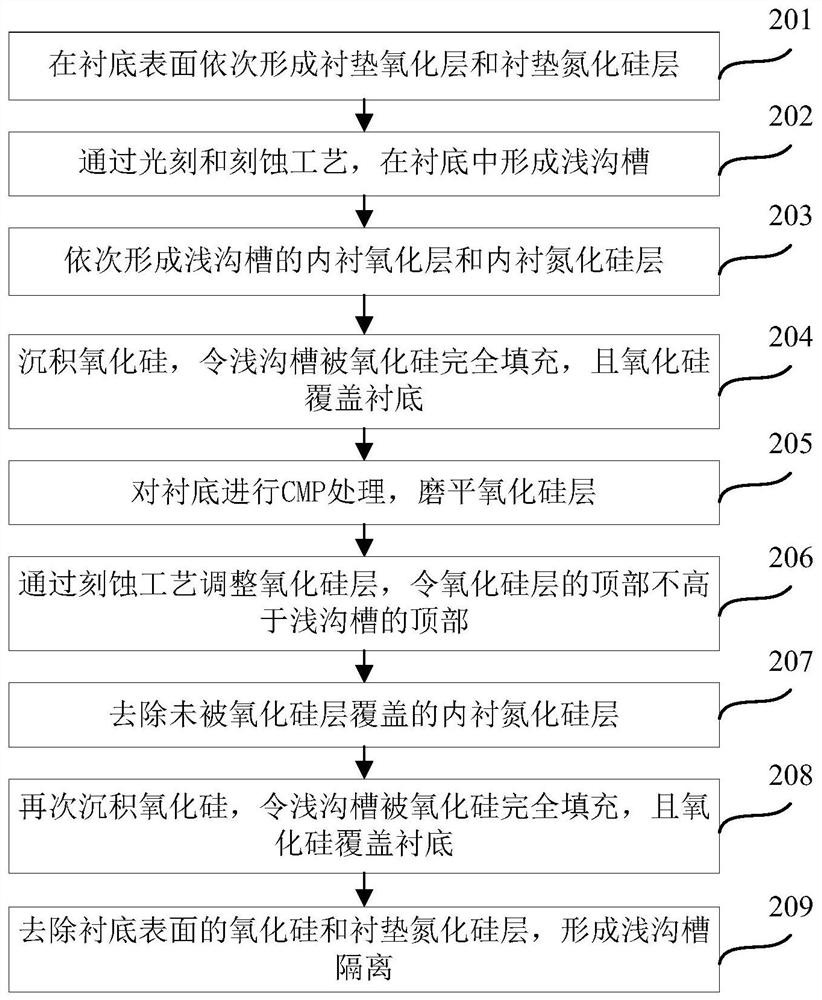
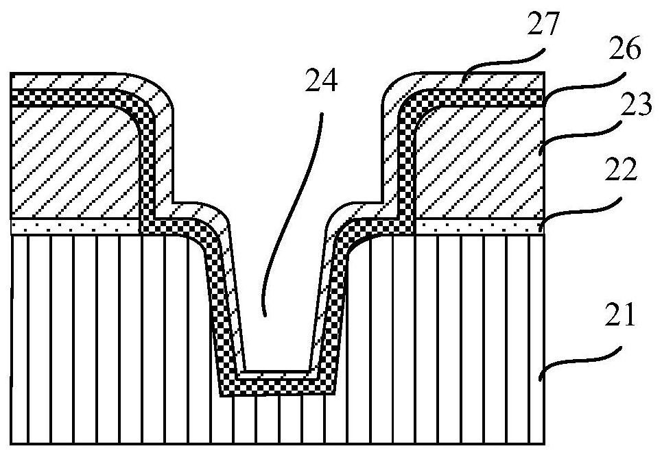
The invention discloses an STI forming method, and relates to the field of semiconductor manufacturing. The method comprises the following steps: forming a liner oxide layer and a liner silicon nitride layer on the surface of a substrate; forming a shallow trench in the substrate through photoetching and etching processes; forming a lining oxide layer and a lining silicon nitride layer of the shallow trench; depositing silicon oxide to enable the shallow trench to be completely filled with the silicon oxide, and enabling the silicon oxide to cover the substrate; carrying out CMP treatment on the substrate; adjusting the silicon oxide layer through an etching process to make the top of the silicon oxide layer not higher than the top of the shallow trench; removing the lining silicon nitride layer which is not covered by the silicon oxide layer; depositing silicon oxide again to enable the shallow trench to be completely filled with the silicon oxide, and enabling the silicon oxide to cover the substrate; and removing the silicon oxide on the surface of the substrate and the liner silicon nitride layer to form shallow trench isolation. The problem that the vertex angle of the shallow trench isolation is easy to be sunken due to the fact that the redundant silicon nitride layer on the surface of the substrate is removed through a wet etching process is solved. And the effect of improving the performance of the device is achieved.

Description

technical field [0001] The present application relates to the field of semiconductor manufacturing, in particular to a method for forming an STI. Background technique [0002] As the size of semiconductor devices continues to decrease, the size of isolation regions between devices also decreases accordingly. Currently, STI (shallow trench isolation, shallow trench isolation) is mostly used to implement isolation between devices. [0003] In the manufacture of CMOS image sensors, as the size of the pixel area decreases, the lining oxide layer in the STI cannot effectively block more and more charges from crossing, resulting in dark current at the charge escape interface, which affects the pixel quality. In order to reduce the influence of dark current on device performance, when forming STI, a lining silicon nitride layer is formed on the lining oxide layer, and the lining silicon nitride layer is used to absorb charges and prevent charge from escaping. [0004] However, wh...

Claims


Application Information

Patent Timeline
IPC IPC(8): H01L21/762H01L27/146
CPCH01L27/1463H01L21/76237H01L21/76224
Inventor 肖敬才邱元元郭振强黄鹏
Owner HUA HONG SEMICON WUXI LTD
Learn More