
Electric connector

A technology for electrical connectors and contact parts, which is applied in the direction of connection, parts and circuits of connecting devices, and can solve the problems of data transmission, loss of transmission, errors, etc.

Active Publication Date: 2021-06-08
DONGGUAN LUXSHARE TECH CO LTD
View PDF7 Cites 0 Cited by
  • Summary
  • Abstract
  • Description
  • Claims
  • Application Information

AI Technical Summary

Problems solved by technology

This inductive signal may cause loss of data transmission and transmission errors

Method used


Image

  • Electric connector
  • Electric connector
  • Electric connector

Examples


Embodiment Construction

[0023] A number of implementations of the present application will be disclosed in the following figures. For the sake of clarity, many implementation details will be described together in the following description. However, it should be understood that these implementation details should not be used to limit the application. That is to say, in some embodiments of the present application, these implementation details are unnecessary. In addition, for the sake of simplifying the drawings, some well-known and commonly used structures and components will be shown in a simple schematic manner in the drawings. In the following embodiments, the same or similar components will be denoted by the same reference numerals.

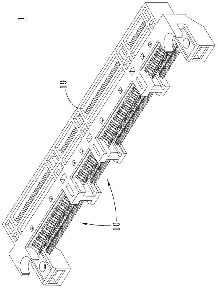
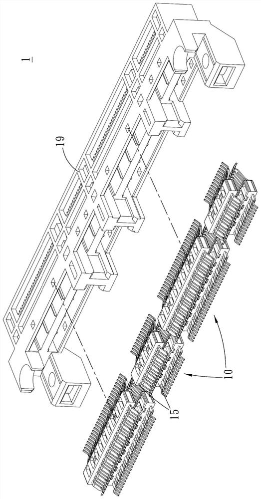
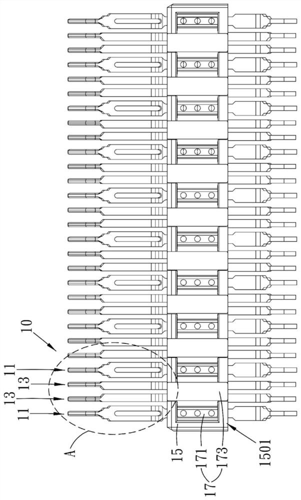
[0024] see Figure 1 to Figure 4 , figure 1 is a perspective view of the electrical connector of the present application, figure 2 is an exploded view, image 3 is a schematic diagram of the terminal module with Figure 4 yes image 3 Enlarged view of area A....


PUM


Abstract

The invention discloses an electric connector. The electric connector comprises a terminal module. The terminal module comprises a grounding terminal and a signal terminal arranged side by side with the grounding terminal, the grounding terminal is provided with a first contact part, the signal terminal is provided with a second contact part, and the outer diameter width of the first contact part is larger than that of the second contact part. The contact end of the grounding terminal is wider than the contact end of the signal terminal, the distance from the contact end of the signal terminal to the contact end of the adjacent grounding terminal is shortened by increasing the width of the contact end of the grounding terminal, the backflow path of the signal terminal is shorter, more energy is bound between the signal terminal and the grounding terminal, and therefore, excessive interference of a surrounding magnetic field is avoided, and the crosstalk problem can be effectively solved.

Description

technical field [0001] The present application relates to the technical field of connectors, in particular to an electrical connector. Background technique [0002] In the prior art, crosstalk is one of the relevant important problems affecting the design of electrical connectors, because of the coupling phenomenon between two signal lines. This is because the spatial distance between the two signal lines is close, which will cause inductive and capacitive coupling between the signal lines to interfere with each other. Capacitive coupling induces a coupled current, while inductive coupling induces a coupled voltage. Crosstalk may affect the high-speed transmission of data. It is the energy value of a kind of interference generated by the coupling of one signal to another signal. As long as there is a current, there will be a magnetic field, and the interference between the magnetic fields is the source of crosstalk. This inductive signal may cause loss of data transmissio...

Claims


Application Information

Patent Timeline
Patent Type & Authority Applications(China)
IPC IPC(8): H01R13/652H01R13/6461
CPCH01R13/652H01R13/6461H01R13/6471H01R13/6474
Inventor 陈宏基程恒山贺云峰
Owner DONGGUAN LUXSHARE TECH CO LTD
Learn More