Cooling circulation loop for high-power high-speed submersible pump

A cooling cycle, submersible pump technology, applied in cooling/ventilation devices, casings/covers/supports, electrical components, etc., can solve the problems of cooling failure and easy failure of the upper sliding bearing

Active Publication Date: 2021-06-08
NANJING INST OF TECH
View PDF7 Cites 2 Cited by
  • Summary
  • Abstract
  • Description
  • Claims
  • Application Information

AI Technical Summary

Problems solved by technology

[0003] Aiming at the problem that the cooling liquid in the cooling circulation circuit set in the above-mentioned submersible pump is easily caused by the excessive heat generation at the air gap of the motor, the cooling failure of the upper sliding bearing is easily caused, especially in the state of high power, the present invention Propose a Cooling Circulation Circuit for High Power High Speed ​​Submersible Pump

Method used


Image

  • Cooling circulation loop for high-power high-speed submersible pump
  • Cooling circulation loop for high-power high-speed submersible pump
  • Cooling circulation loop for high-power high-speed submersible pump

Examples


Embodiment Construction

[0029] In order to make the object, technical solution and advantages of the present invention more clear, the present invention will be further described in detail below in conjunction with the examples. It should be understood that the specific embodiments described here are only used to explain the present invention, not to limit the present invention.

[0030] The application principle of the present invention will be described in detail below in conjunction with the accompanying drawings.

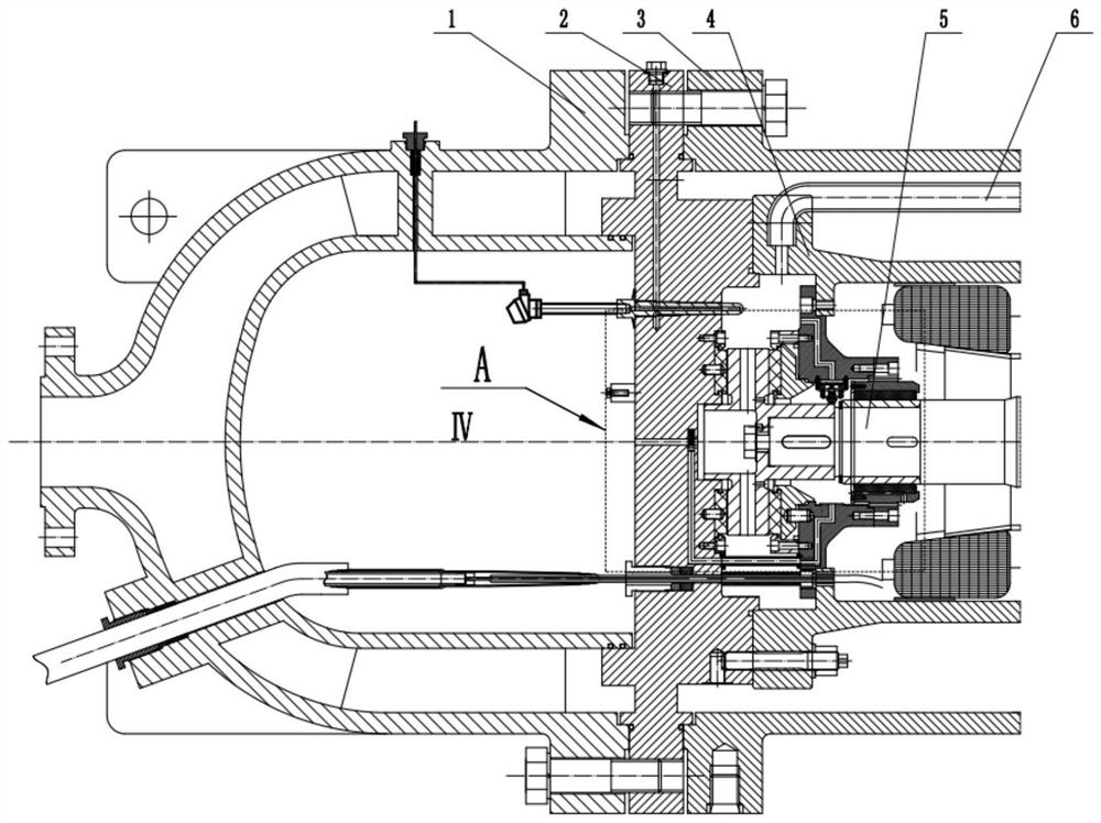
[0031] like Figure 1-5 As shown, at the starting left end of the pump along the axial direction of the unit, from left to right, install the motor bottom cover 1, the motor end cover 2, and the motor outer wall 3 in sequence, and connect them through fasteners to form the entire unit. The outer end and the left cavity of the motor. The motor inner wall 4 is located on the right side of the motor end cover 2, and is connected with the motor end cover 2 by fasteners, forms the right c...


PUM


Abstract

The invention discloses a cooling circulation loop for a high-power high-speed submersible pump. The cooling circulation loop comprises a first cavity, a second cavity, a third cavity and a fourth cavity which are arranged in the submersible pump. The cooling circulation loop comprises a first through hole A and a first through hole B which are arranged in the bearing support, and a connecting hole A and a connecting hole B which are arranged in the motor end cover, two ends of the first through hole A are communicated with the second chamber and the third chamber, and two ends of the first through hole B are respectively communicated with the third chamber and the connecting hole A; the two ends of a connecting hole B are communicated with the first cavity and the fourth cavity, the connecting hole B is further perpendicularly intersected with the connecting hole A, a first control valve for controlling connection and disconnection of the connecting hole A and the connecting hole B is arranged at the intersection point of the connecting hole B and the connecting hole A, and a second control valve for controlling connection and disconnection of the first through hole A and the third cavity is further arranged in the third cavity.

Description

technical field [0001] The invention belongs to the field of fluid machinery, and in particular relates to a cooling circulation circuit for a high-power high-speed submersible pump. Background technique [0002] The high-power high-speed submersible pump uses a wet motor to ensure the reliability of the unit. In the existing unit, an independent internal cooling cycle is used to cool and dissipate the wet motor, and at the same time cool and lubricate the bearings and other components. The specific circulation mode is that the thrust plate set at one end of the motor cavity serves as the auxiliary impeller to provide power source, the coolant reaches the end of the motor cavity away from the thrust plate through the cooling circulation pipe, and then returns to the motor cavity through the lower sliding bearing, motor air gap, upper sliding bearing and other areas. The thrust disc forms a cooling circuit. In this circuit mode, the coolant flowing out from the supply end ne...

Claims


Application Information

Patent Timeline
Patent Type & Authority Applications(China)
IPC IPC(8): H02K9/19H02K5/132H02K5/20
CPCH02K5/132H02K5/20H02K9/19
Inventor 柏宇星杨雪梅许丽娇苗婧孙铖涛王义云董千
Owner NANJING INST OF TECH
Why Eureka
Try Eureka