Flat mop suite

A flat mop and mop technology, which is applied in the field of mop buckets, can solve the problems of inconvenient cleaning, unsatisfactory use effect, affecting the normal movement of the piston, etc., and achieves the effect of reducing the number of parts, avoiding sanitary dead corners, and reducing assembly steps.

Inactive Publication Date: 2021-06-11
HANGZHOU YUNFENG IND DESIGN CO LTD
View PDF1 Cites 2 Cited by
  • Summary
  • Abstract
  • Description
  • Claims
  • Application Information

AI Technical Summary

Problems solved by technology

[0004] However, the problem with the above scheme is that when the mop is cleaned in the inner cylinder, some of the dirt carried on the mop will fall into the inner cylinder, which will affect the normal movement of the piston, and because the water squeezing device also needs to be provided with two one-way Only the valve can ensure the normal operation of the water squeezing device, and the one-way valve is connected with the mop bucket, the dirt in the mop bucket will also affect the normal operation of the one-way valve, and there is obviously the problem of inconvenient cleaning, and the use effect is not ideal

Method used


Image

  • Flat mop suite
  • Flat mop suite
  • Flat mop suite

Examples


Embodiment 1

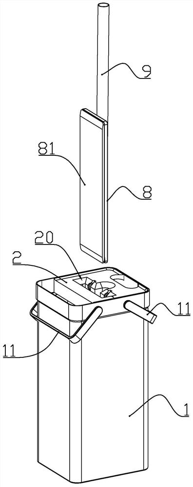
[0024] according to Figure 1 to Figure 8 As shown, this embodiment is a flat mop kit, including a mop and a mop bucket; the mop includes a mop board with wipes, and a mop bar movably connected with the mop board.

[0025] The wiper is a mop or collodion of a common flat mop on the market. A rotary joint is rotatably connected to the middle of the mop board, the lower end of the mop rod is rotatably connected to the rotary joint, and the rotation axis a of the mop rod and the rotary joint and the rotation axis b of the mop plate and the rotary joint are perpendicular. When the mop needs to be washed or squeezed dry, turn the mop plate to figure 1 Shown approximately parallel to the mop bar. The upper end of the mop board and the upper end of the wipes described below generally refer to the end of the mop bar that is placed vertically and the mop board is turned to be parallel to the mop bar and faces upward.

[0026] The mop bucket includes a bucket body 1 and an inner buc...

Embodiment 2

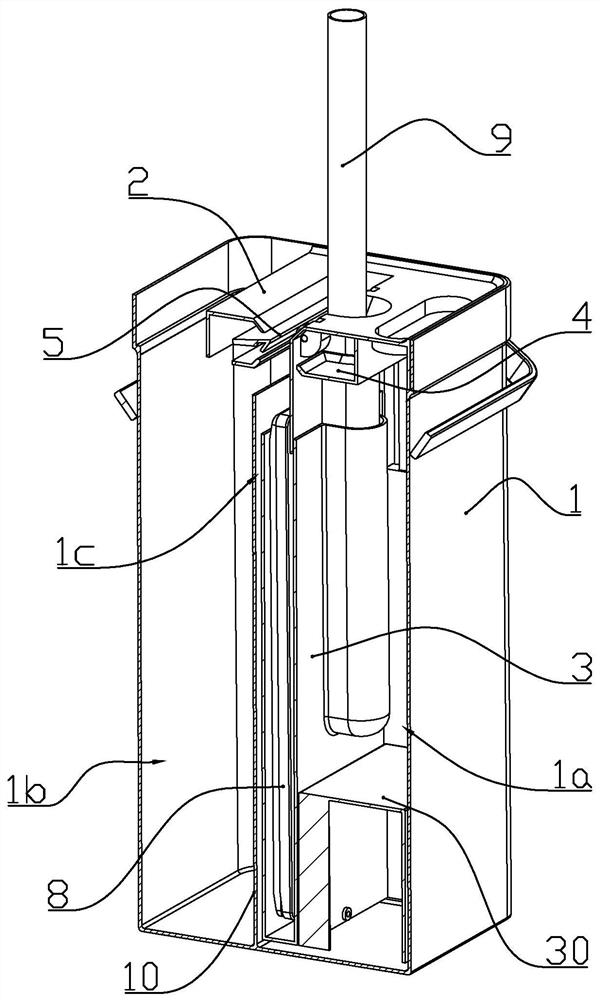
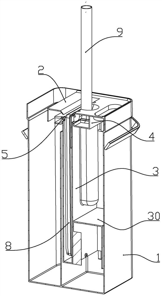
[0058] combine Figure 9 to Figure 11 As shown in the figure, the difference between this embodiment and Embodiment 1 is that a water guide tube 6 is arranged in the clean water container, the inner barrel is slid in the water guide tube along the longitudinal direction, and the inner wall of the water guide tube is connected to the outer wall of the inner barrel. A water supply channel 1c is formed therebetween; and the water guide tube is provided with a water passage 61, which makes the water guide tube communicate with the clean water chamber. In this case, the inner tub itself acts as the flow blocking member, that is, when the side wall of the inner tub blocks the water passage, it prevents or slows the rise of the water level in the clean water chamber.

[0059] Further, the water guide tube described in the figure is a structure that is detachably installed in the barrel. In some other embodiments, the water guide tube can be integrally formed with the tub body. That...


PUM


Abstract

The invention discloses a flat mop suite. The flat mop suite comprises a mop and a mop bucket; the mop bucket comprises a bucket body and an inner bucket mounted in the bucket body; a clean water containing cavity and a sewage containing cavity are formed in the barrel body, the water feeding channel is arranged in the range of the barrel body, the lower end of the water feeding channel is communicated with the clean water containing cavity, the upper end of the water feeding channel is communicated with an opening in the upper end of the inner barrel, the inner barrel is provided with a flow blocking component, and in the process of the inner barrel moving downwards relative to the clean water containing cavity, the water level in the water feeding channel rises to exceed the opening in the upper end of the inner barrel through the flow blocking component, so that water in the water feeding channel is poured into the inner barrel; a squeezer for cleaning and / or squeezing the wiping object is arranged above the opening in the upper end of the inner barrel on the barrel body; and when the mop plate moves upwards and / or downwards relative to the squeezer, water adsorbed on the wiping object can be squeezed out by the squeezer and discharged into the sewage containing cavity. The mop can be cleaned with clean water, the structure is simple, and operation is convenient.

Description

technical field [0001] The invention belongs to the field of cleaning tools, and in particular relates to a flat mop and a mop bucket for supporting use. Background technique [0002] The Chinese patent with the patent number of CN201721692243.1 discloses a cleaning tool, which includes a flat mop and a mop bucket. The flat mop includes a mop bar and a flat mop head movably arranged on the mop bar. The barrel, the inner barrel and the mop barrel are independent of each other, the upper port of the inner barrel is provided with a squeezing device adapted to the flat mop head, and a water squeezing device is arranged between the inner barrel and the mop barrel, and the squeezing device squeezes the liquid in the mop barrel. Injected into the inner cylinder, the present invention provides a simple and stable cleaning tool with convenient operation. [0003] The advantage of the above-mentioned patent solution is that the mop is cleaned and squeezed out in the inner cylinder, a...

Claims


Application Information

Patent Timeline
Patent Type & Authority Applications(China)
IPC IPC(8): A47L13/20A47L13/254A47L13/58
CPCA47L13/20A47L13/254A47L13/58
Inventor 曲淑华
Owner HANGZHOU YUNFENG IND DESIGN CO LTD
Why Eureka
Try Eureka