
Continuous punching equipment for pipes

A technology for punching and pipes, applied in the direction of pushing out equipment, metal processing equipment, feeding devices, etc., can solve the problems of low efficiency, low degree of automation, and inability to realize continuous punching of pipes, etc., to achieve strong continuity and high efficiency Effect

Pending Publication Date: 2021-06-11
HUIZHOU ZHIJING PRECISION TECH CO LTD
View PDF0 Cites 1 Cited by
  • Summary
  • Abstract
  • Description
  • Claims
  • Application Information

AI Technical Summary

Problems solved by technology

[0002] Pipe punching, that is, opening holes on the pipe wall, is generally completed by a punching machine, but its degree of automation is not high, and it is necessary to manually put the pipe into the punching machine, which is inefficient and cannot achieve continuous punching of the pipe

Method used


Image

  • Continuous punching equipment for pipes
  • Continuous punching equipment for pipes
  • Continuous punching equipment for pipes

Examples


Embodiment Construction

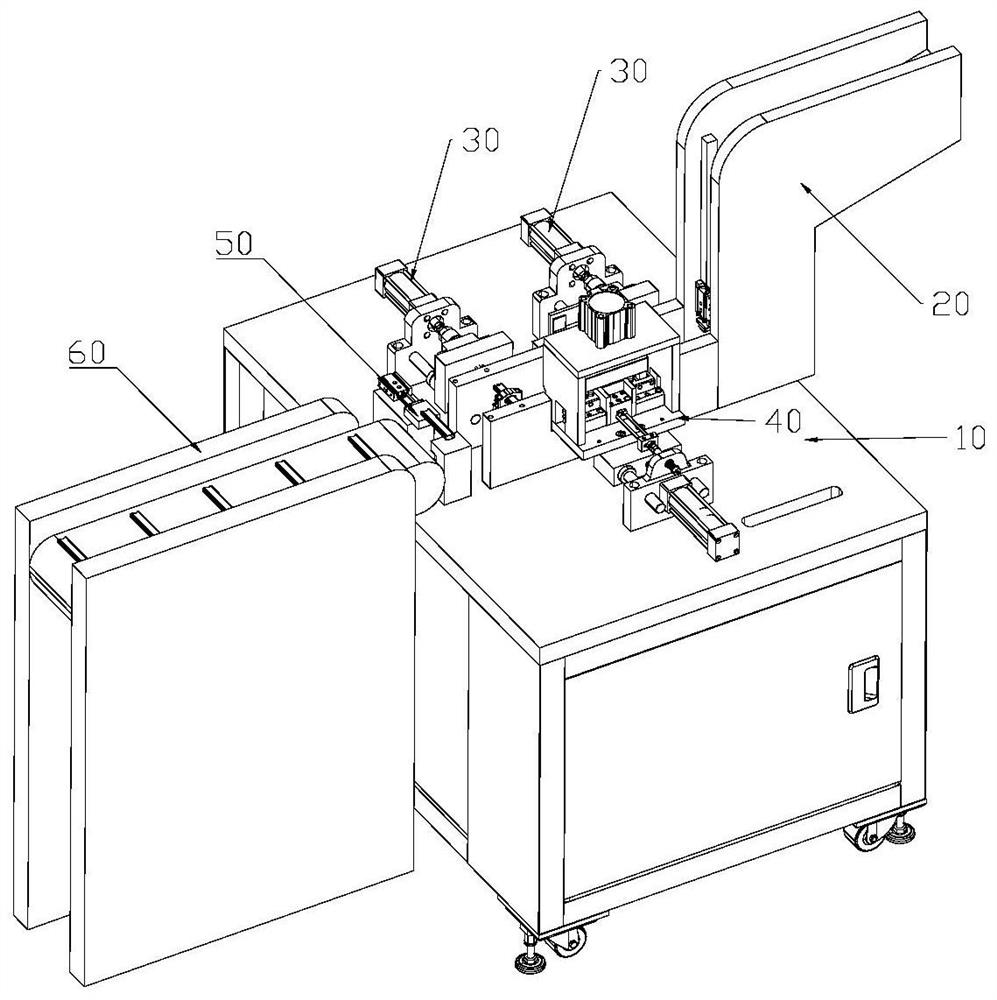
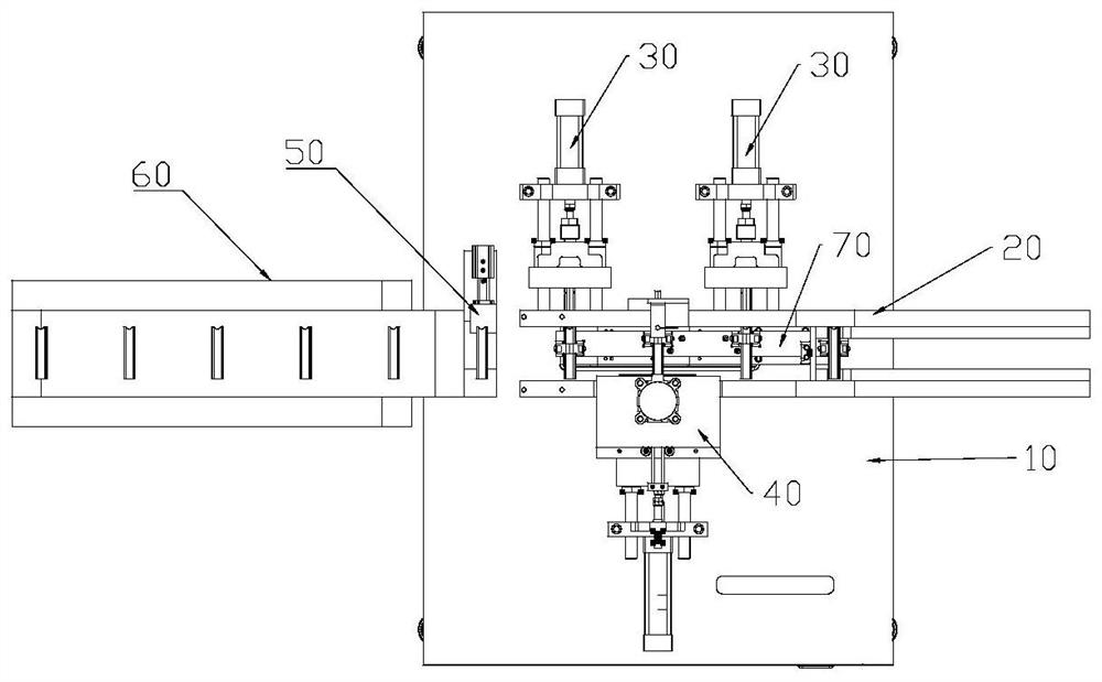
[0048] see Figure 1-2 , the present embodiment provides a continuous punching equipment for pipes, which includes: a frame 10, a feeding mechanism 20, two positioning mechanisms 30, a punching mechanism 40, a defective product removal mechanism 50, a feeding mechanism 60 and A transfer mechanism 70 .

[0049]The frame 10 is sequentially provided with a loading station, a first positioning station, a punching station, a second positioning station, a defective product removal station and a blanking station; the feeding mechanism 20 is arranged on The loading station is used to load pipes; one positioning mechanism 30 is arranged at the first positioning station, and the other positioning mechanism 30 is arranged at the second positioning station; the positioning mechanism 30 is used to fix the pipe; the punching mechanism 40 is arranged at the punching station for detecting pipes and opening holes for qualified pipes; the defective product removal mechanism 50 is arranged at t...


PUM


Abstract

The invention provides continuous punching equipment for pipes. The continuous punching equipment for the pipes comprises a rack, a feeding mechanism, two positioning mechanisms, a punching mechanism, a defective product removing mechanism, a discharging mechanism and a conveying mechanism. The feeding mechanism is arranged at a feeding station; one positioning mechanism is arranged at a first positioning station, and the other positioning mechanism is arranged at a second positioning station; the punching mechanism is arranged at a punching station; the defective product removing mechanism is arranged at a defective product removing station; the discharging mechanism is arranged at a discharging station. and the conveying mechanism is arranged in the rack. Compared with the prior art, the continuous punching equipment for the pipes provided by the invention has the advantages that pipe punching can be completed only by loading a pipe into the feeding mechanism and starting the equipment, so that the continuity is high, the efficiency is high, the qualification of the pipe can be detected, and the qualified pipe can be punched.

Description

technical field [0001] The invention relates to the technical field of pipe punching, in particular to continuous punching equipment for pipes. Background technique [0002] Pipe punching, that is, opening holes on the pipe wall, is generally completed by a punching machine, but its automation is not high, and the pipe needs to be manually put into the punching machine, which is inefficient and cannot achieve continuous punching of the pipe. Contents of the invention [0003] The object of the present invention is to provide a pipe continuous punching equipment to solve the shortcomings and deficiencies in the prior art. [0004] A pipe continuous punching equipment of the present invention comprises: a frame, a feeding mechanism, two positioning mechanisms, a punching mechanism, a defective product removal mechanism, a feeding mechanism and a transmission mechanism; [0005] The frame is sequentially provided with a loading station, a first positioning station, a punchin...

Claims


Application Information

Patent Timeline
IPC IPC(8): B21D28/28B21D43/10B21D43/00B21D45/02B21C51/00B07C5/36
CPCB07C5/362B21C51/00B21D28/28B21D43/003B21D43/006B21D43/10B21D45/02
Inventor 伍飒王绪明
Owner HUIZHOU ZHIJING PRECISION TECH CO LTD
Learn More