
Automatic welding equipment

An automatic welding and equipment technology, applied in the field of welding processing, can solve the problems of low welding efficiency, heavy workload, and low placement efficiency

Pending Publication Date: 2021-06-11
VICHNET COMM SCI & TECH
View PDF15 Cites 7 Cited by
  • Summary
  • Abstract
  • Description
  • Claims
  • Application Information

AI Technical Summary

Problems solved by technology

[0004] However, the above-mentioned processing method mainly has the following defects: 1. It is necessary to manually arrange the longitudinal ribs and transverse ribs, the workload is large, the placement efficiency is low, and it is easy to tilt, thereby reducing the processing quality of the grid bridge; 2. Due to There are many intersecting points of transverse ribs and longitudinal ribs, the workload of manual welding is large, and the welding efficiency is low; 3. When the grid surface formed by the arrangement of longitudinal ribs and transverse ribs is large, the peripheral transverse ribs and longitudinal ribs It is easy to cause interference to the welding operation, further reducing the efficiency of the welding operation

Method used


Image

  • Automatic welding equipment
  • Automatic welding equipment
  • Automatic welding equipment

Examples


Embodiment 1

[0068] Embodiment one: if Figure 14-18 As shown, it includes a first drive mechanism 7 for driving the second welding seat 21 to move up and down and a second drive mechanism 8 for driving the push block 47 to slide longitudinally. like Figure 14 as well as Figure 17-18 As shown, the first drive mechanism 7 includes a drive shaft 71, a fixed mount 72, a first cam 73, a pull rod 74 and a compression spring 75, the drive shaft 71 is longitudinally arranged on the frame 1, and the first cam 73 is arranged on the drive shaft 71 A plurality of second welding seats 21 are longitudinally spaced on the fixed frame 72, and the fixed frame 72 is arranged on the frame 1 sliding up and down; the pull rod 74 is arranged on the frame 1 sliding up and down, and the upper end of the pull rod 74 is connected to the Frame 72; stage clip 75 is arranged on the frame 1, and forces the lower end of pull bar 74 to contact with the outer ring surface of first cam 73 (for example, stage clip 75 p...

Embodiment 2

[0071] Embodiment two: if Figure 21-22 As shown, both the pushing block 47 and the second welding seat 21 are driven by the driving cylinder 9 , so that the driving block 47 and each second welding seat 21 can be controlled to move independently by the driving cylinder 9 .

[0072] In the second embodiment, if Figure 22 As shown, the welding mechanism 2 also includes a first wiring board 22, a second wiring board 23 and a plurality of bendable conductors 24, the first wiring board 22 and the second wiring board 23 are both arranged on the frame 1, The first wiring board 22 communicates with the plurality of first welding seats 20 , and the second wiring board 23 communicates with the plurality of second welding seats 21 through a plurality of conductors 24 respectively. When the driving cylinder 9 drives the second welding seat 21 to move downward until the longitudinal rib 102 and the transverse rib 101 are pressed on the first welding seat 20, the first wiring board 22, t...


PUM


Abstract

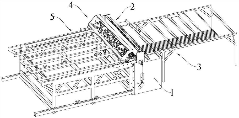
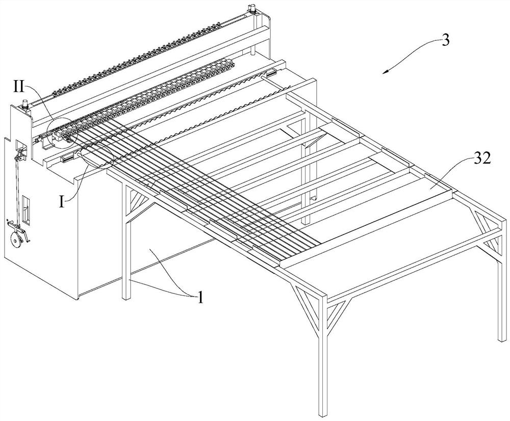
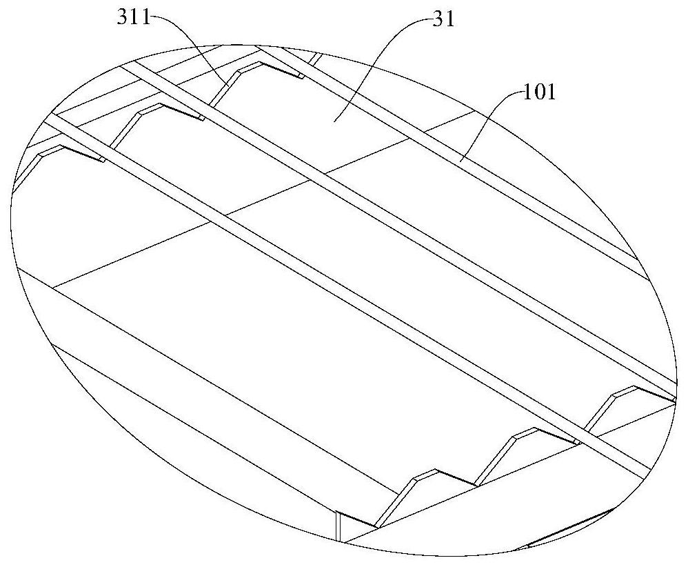
The invention discloses automatic welding equipment which comprises a rack, a welding mechanism, a first feeding mechanism, a second feeding mechanism, a traction mechanism, an automatic discharging mechanism and a storage area. The welding mechanism comprises multiple first welding bases and multiple second welding bases which are longitudinally arranged on the rack at intervals; the second welding bases are arranged over the first welding bases in a one-to-one correspondence mode and can move up and down; the first feeding mechanism is used for conveying multiple transverse ribs to the upper ends of the multiple first welding bases in a one-to-one correspondence mode; the second feeding mechanism is used for alternately conveying single longitudinal ribs to the upper ends of the multiple first welding bases at intervals; the traction mechanism comprises a moving track, a traction frame and a clamp; the traction frame can transversely slide on the moving track; the clamp is arranged on the traction frame and used for clamping the longitudinal ribs; and the automatic discharging mechanism is used for automatically conveying steel wire frameworks located on the moving track to the storage area. The automatic welding equipment is simple to operate, high in automation degree, high in production efficiency, low in labor demand and suitable for industrial production.

Description

technical field [0001] The present application relates to the technical field of welding processing, in particular to an automatic welding equipment. Background technique [0002] At present, grid bridges are usually used for support and protection when laying cables, communication optical cables or other long and thin pipes. The existing grid bridge is generally a grid-like structure with a "匚"-shaped structure, and the inside of the "匚"-shaped structure can be used for laying cables, communication optical cables or other long and thin pipes. [0003] When processing grid bridges with a "匚"-shaped structure, it is necessary to manually arrange the longitudinal ribs and transverse ribs at equal intervals to form a grid structure, and then use a welding machine to weld at the junction of the transverse ribs and longitudinal ribs, and finally The welded mesh structure is bent to form a "匚"-shaped structure. [0004] However, the above-mentioned processing method mainly has t...

Claims


Application Information

Patent Timeline
Patent Type & Authority Applications(China)
IPC IPC(8): B21F27/10B21F23/00B21F27/12
CPCB21F27/10B21F23/00B21F27/12
Inventor 俞波闻丽君李肖叶琪珺陈志强
Owner VICHNET COMM SCI & TECH
Learn More