Flexible welding tool for main stand column structure of lifting cage and welding construction method

A welding tool and main column technology, applied in welding equipment, auxiliary welding equipment, welding/cutting auxiliary equipment, etc., can solve the problems of deformation production efficiency, reduce production efficiency, time-consuming and labor-intensive, etc., and achieve simple tool welding and easy demoulding. The effect of pickup

Pending Publication Date: 2021-06-11
GUANGXI CONSTR ENG GROUP CONSTR MACHINERY MFG
View PDF0 Cites 4 Cited by
  • Summary
  • Abstract
  • Description
  • Claims
  • Application Information

AI Technical Summary

Problems solved by technology

At present, the manufacture of most hanging cages uses parts to be positioned and welded into parts, and then the parts are positioned and welded to form a whole. This manufacturing process is a tooling welding corresponding to a main column structure of the hanging cage. The welding process has low precision and large errors.
Secondly, the welding tool has no flip function, and it is inconvenient to weld the reverse side, resulting in time-consuming and labor-intensive work, which reduces production efficiency, and demoulding welding is easy to deform, and repeated processing is prone to deformation and low production efficiency, and the requirements for manufacturing workers are relatively high.

Method used


Image

  • Flexible welding tool for main stand column structure of lifting cage and welding construction method
  • Flexible welding tool for main stand column structure of lifting cage and welding construction method
  • Flexible welding tool for main stand column structure of lifting cage and welding construction method

Examples


Embodiment Construction

[0025] In order to make the object, technical solution and advantages of the present invention clearer, the present invention will be described in further detail below with reference to the accompanying drawings and preferred embodiments. However, it should be noted that many of the details listed in the specification are only for readers to have a thorough understanding of one or more aspects of the present invention, and these aspects of the present invention can be implemented even without these specific details.

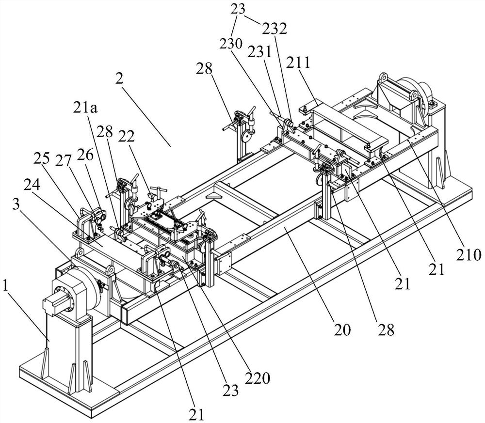
[0026] combine figure 1 As shown, a flexible welding tooling for the main column structure of an elevator cage according to the present invention includes a welding positioner 1, a tooling quick change mechanism 3 and a tooling platform 2 for clamping and fixing the main column structure of the hanging cage. The two ends of the platform 2 are respectively detachable to the tooling quick change mechanism 3, and the tooling quick change mechanism 3 at both ends of ...


PUM


Abstract

The invention discloses a flexible welding tool for a main stand column structure of a lifting cage and a welding construction method. The flexible welding tool for the main stand column structure of the lifting cage comprises a welding positioner, tool quick-changing mechanisms and a tool platform used for clamping and fixing the main stand column structure of the lifting cage, wherein the tool quick-changing mechanisms are detachably arranged at the two ends of the tool platform correspondingly; the tool quick-changing mechanisms at the two ends of the tool platform are rotatably installed on the welding positioner, the two ends of a horizontal supporting bottom frame are rotatably installed on the welding positioner through the tool quick-changing mechanisms, and a plurality of detachable fixed positioning seats are transversely arranged on the upper surface of the edge of the horizontal supporting bottom frame at intervals; a plurality of movable clamping mechanisms which slide back and forth in the center direction of the horizontal supporting bottom frame are symmetrically arranged on the inner side of the edge of the horizontal supporting bottom frame, and first fixed clamping mechanisms are arranged at the two ends of the fixed positioning seats. According to the flexible welding tool for the main stand column structure of the lifting cage, the inner side direction, the outer side direction and the top of the main stand column structure of the lifting cage can be rapidly pressed and positioned, and overturning construction welding can be rapidly conducted.

Description

technical field [0001] The invention relates to the technical field of construction elevator equipment, in particular to a flexible welding tool for the main column structure of an elevator cage and a welding construction method. Background technique [0002] With the increasing number of super high-rise buildings, the construction tasks of high-rise buildings are becoming increasingly heavy, so that various construction hoisting machines for transporting construction personnel and construction equipment have been developed and applied in large quantities. The construction elevator undertakes the construction machinery for the vertical transportation of personnel and materials in the construction of high-rise buildings, which can significantly save working hours and improve labor productivity. The key role is that the cage of the existing elevator is welded by a variety of main column mechanisms, and multiple sets of welding tools need to be produced, which makes the welding...

Claims


Application Information

Patent Timeline
Patent Type & Authority Applications(China)
IPC IPC(8): B23K37/047
CPCB23K37/0443B23K37/047
Inventor 胡浪罗宇德覃富德韦亮李华团樊伟杰李凯华覃重闪黄卫国
Owner GUANGXI CONSTR ENG GROUP CONSTR MACHINERY MFG
Why Eureka
Try Eureka