Apparatus for joining two workpiece parts along a weld by means of transmission welding

a technology of transmission welding and workpiece parts, which is applied in the direction of laser beam welding apparatus, lamination, and lamination devices, can solve the problems of increasing the thermal load on the apparatus and laser source, no steps are provided to influence the power density distribution of the laser beam, and the time-consuming and labor-intensive of joining larger surfaces. , to achieve the effect of quick welding and simple construction

Inactive Publication Date: 2015-03-17
JENOPTIK AUTOMATISIERUNGSTECHN
View PDF15 Cites 7 Cited by
  • Summary
  • Abstract
  • Description
  • Claims
  • Application Information

AI Technical Summary

Benefits of technology

[0017]It is the object of the invention to provide an apparatus for transmission welding preferably of workpiece parts extending over large areas by which a weld extending in at least two dimensions, particularly also a closed loop weld, with a sharp boundary and a homogeneous melt can be produced in a reproducible manner. Further, the apparatus should have a simple construction and make it possible to carry out the welding process quickly.

Problems solved by technology

However, joining larger surfaces proves to be very time-consuming.
It is unfavorable in terms of energy efficiency that a portion of the emitted laser beams is not used and, further, is reflected in a more or less diffuse manner, which increases the thermal load on the apparatus and laser source and necessitates additional measures for protecting the operator.
Further, no steps are provided for influencing the power density distribution of the laser beams on the workpiece surface.
It can be assumed that the exacting demands imposed on the material properties and on the functional configuration of the beam modulator, the use of additional optics for homogenizing the laser beam striking the beam modulator, and the preparation of a required control represent a significant expenditure for production of the apparatus.
Moreover, the principle employed for this purpose can only be meaningfully applied for working small workpieces.

Method used


Image

  • Apparatus for joining two workpiece parts along a weld by means of transmission welding
  • Apparatus for joining two workpiece parts along a weld by means of transmission welding
  • Apparatus for joining two workpiece parts along a weld by means of transmission welding

Examples


Embodiment Construction

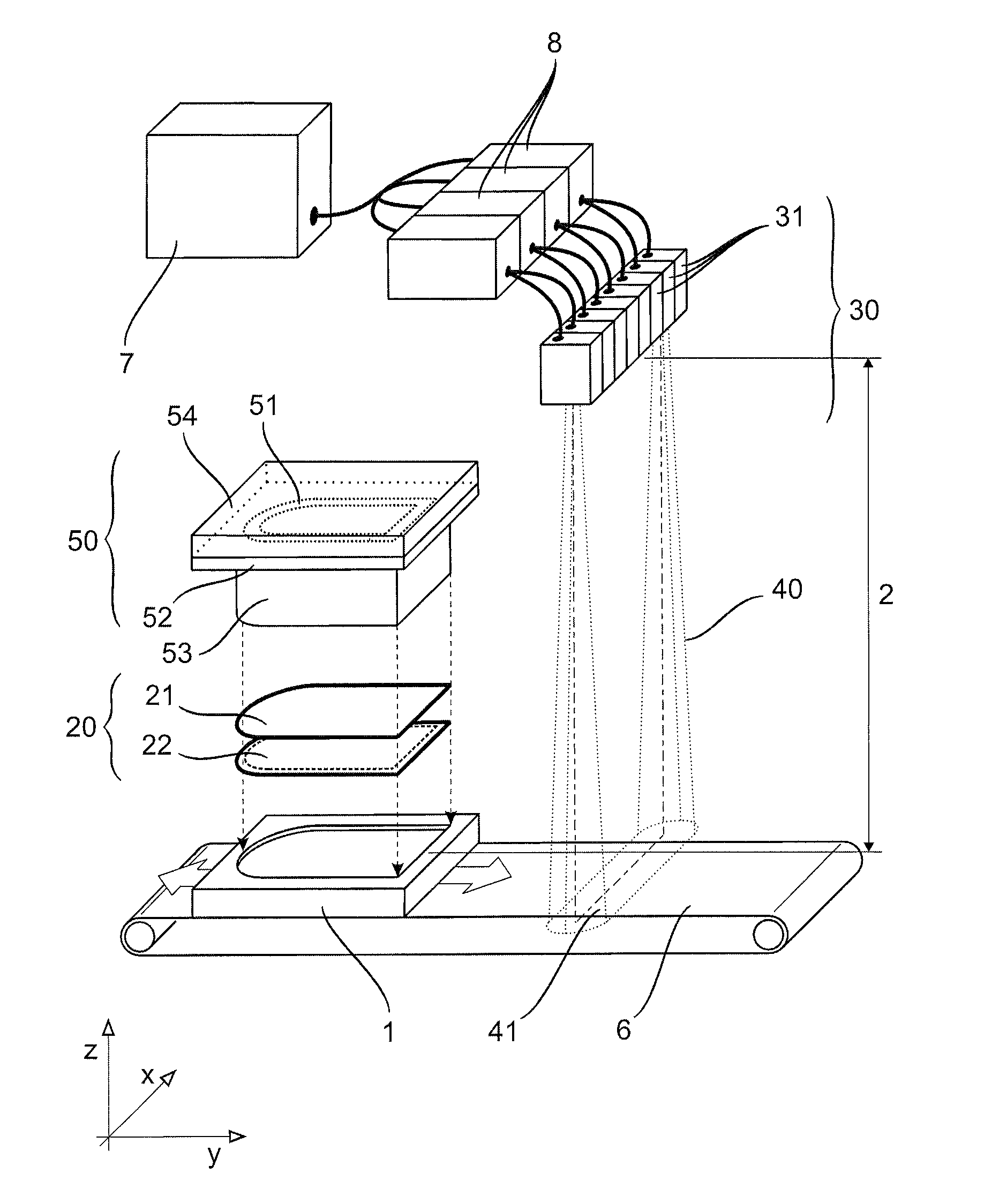
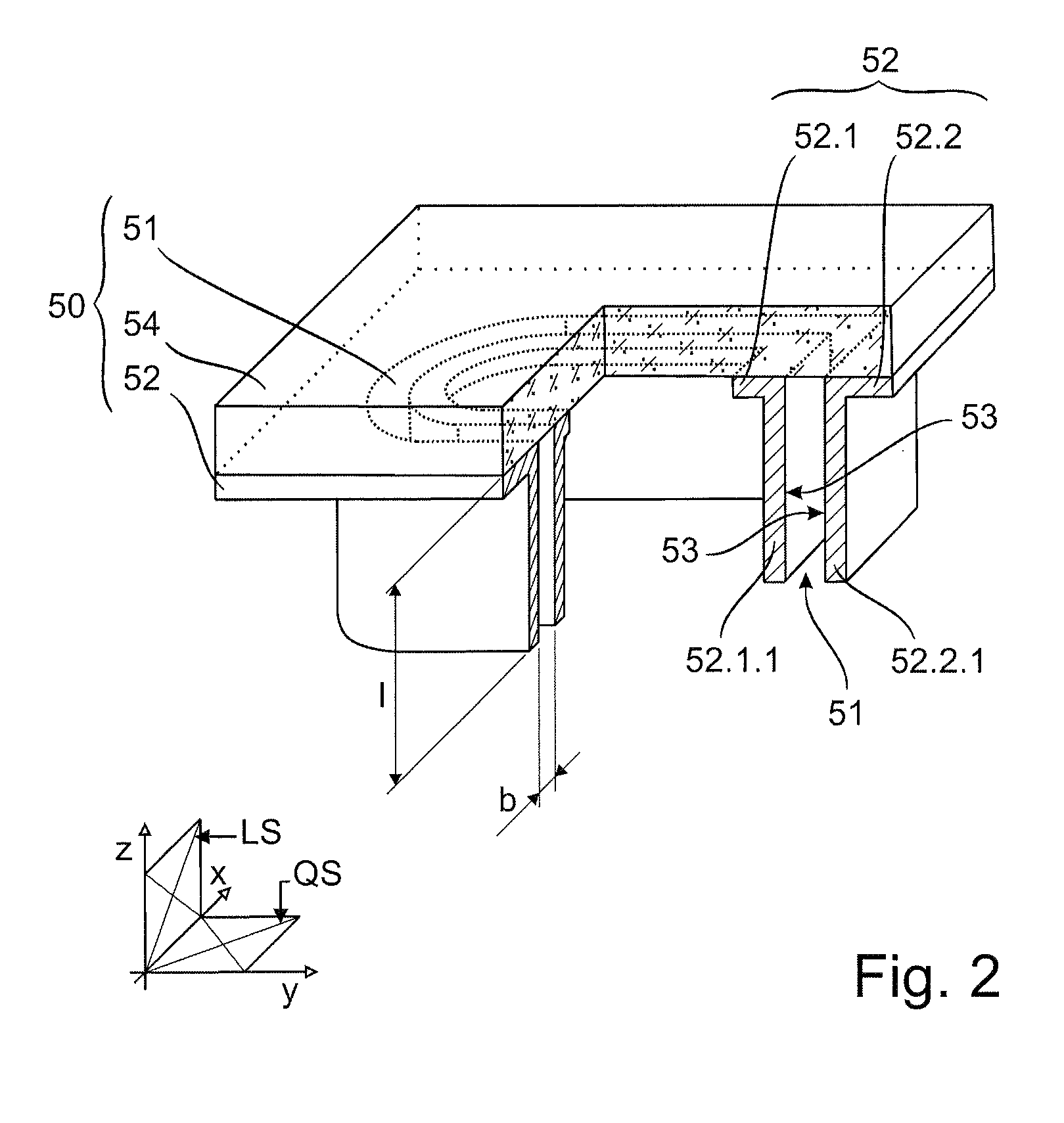
[0023]According to a first embodiment example shown in FIG. 1, the apparatus substantially has a storage-and-control unit 7, a laser beam source 30, a homogenizer 50, a receptacle 1, and a transporting device 6.

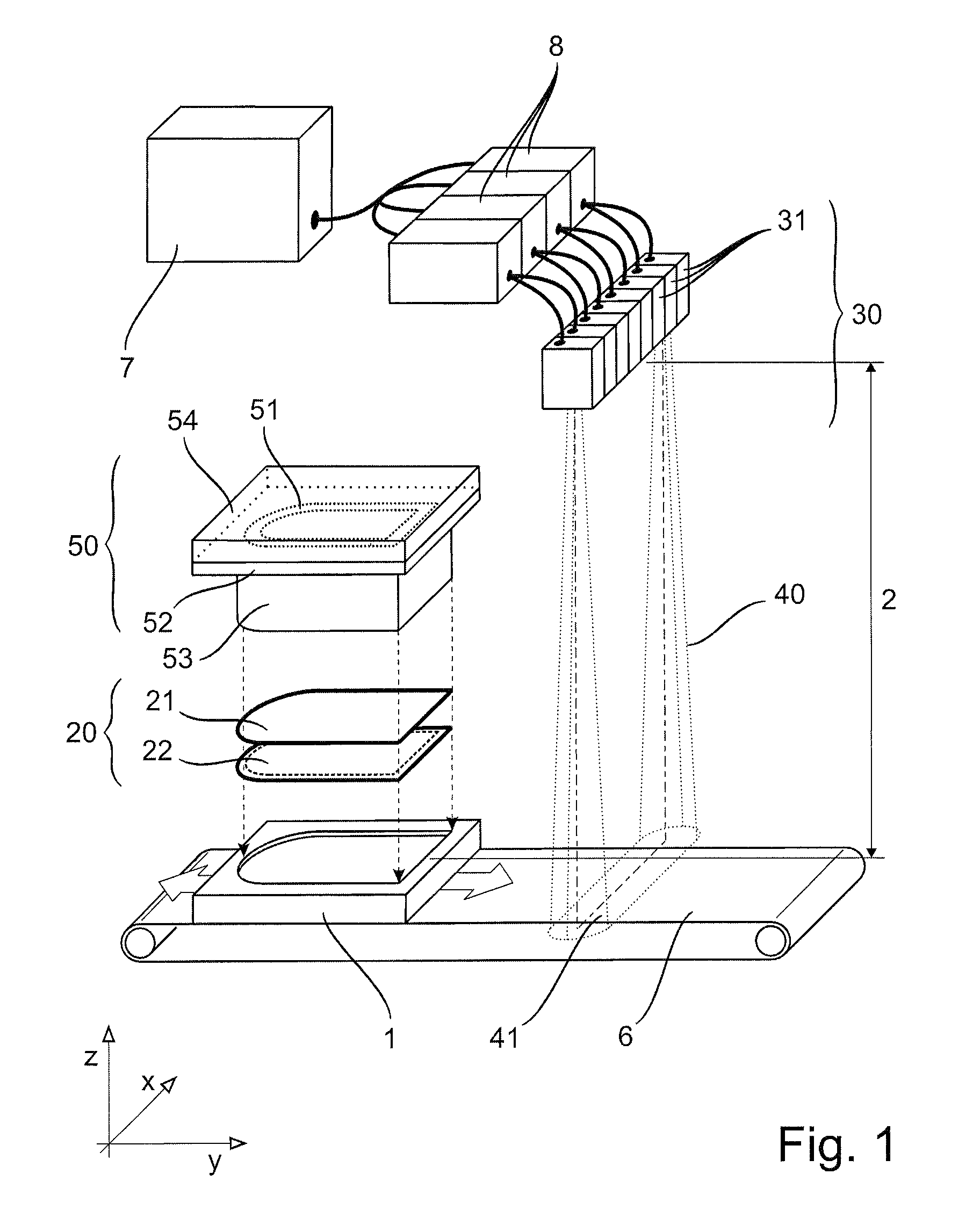
[0024]The receptacle 1 is dimensioned in such a way that a workpiece 20 extending in a planar manner in X and Y direction is positionable therein in the X direction, Y direction and Z direction of a Cartesian coordinate system. The workpiece 20 comprises a transmissive workpiece part 21 and an absorptive workpiece part 22 and is positioned in the receptacle 1 in such a way that the transmissive workpiece part 21 faces the laser beam source 30. The non-transparent homogenizer 50 shielding the workpiece 20 from the effective region 41 of the laser beam source 30 is arranged between the laser beam source 30 and the receptacle 1. This homogenizer 50 has a carrier 52 in which is provided a reflection channel 51 which is continuous in Z direction. The reflection channel 51 has in t...


PUM

PropertyMeasurementUnit
widthaaaaaaaaaa
divergence angleaaaaaaaaaa

Abstract

Apparatus has a receptacle (1) for two workpiece parts (21, 22) which extend two-dimensionally in X and Y directions and which are to be joined along a weld. The apparatus includes a laser beam source (30) comprising a plurality of individually controllable laser beam emitters (31) which collectively form a line array which is oriented in X direction, a transporting device (6) for transporting the laser beam source (30) relative to the receptacle (1) in Y direction, and a homogenizer (50) arranged downstream of the laser beam source (30) in the radiating direction. The homogenizer (50) has a carrier (52) in which is provided at least one reflection channel (51) with a channel cross section (QS) which is adapted to the course of the weld and a channel width (b) which is adapted to the width of the weld.

Description

RELATED APPLICATIONS[0001]The present application claims priority benefit of German Application No. DE 10 2011 055 203.0 filed on Nov. 10, 2011, the contents of which are incorporated by reference in its entirety.BACKGROUND OF THE INVENTION[0002]The invention is directed to an apparatus for joining workpiece parts, preferably workpiece parts extending over a large area, along a joint region (in this instance, at least two-dimensional weld) by means of transmission welding.[0003]Generally, to carry out transmission welding two workpiece parts to be connected to one another are put together in such a way as to directly contact along a contact zone. The joint region lies within the contact zone. The first workpiece part is transmissive for the laser beams and faces a laser source. The second workpiece part is absorptive for the laser beams. The laser beams penetrate the first workpiece part, impinge on the upper layers of the second workpiece part, where they are absorbed and are conve...

Claims


Application Information

Patent Timeline
Patent Type & Authority Patents(United States)
IPC IPC(8): B29C65/16B23K26/06B23K26/08B23K26/20B23K26/24B23K26/32B23K37/04
CPCB23K37/0452B23K26/06B23K26/246B29C65/16B23K26/0608B23K26/0838B23K26/328B23K26/20B23K26/0604B23K26/324B29C65/1635B29C65/1654B29C65/1658B29C65/1664B29C65/1674B29C65/1687B29C65/1696B29C65/7802B29C65/7841B29C65/7864B29C65/787B29C66/112B29C66/1122B29C66/131B29C66/21B29C66/242B29C66/244B29C66/2442B29C66/301B29C66/53461B29C66/73521B29C66/81267B29C66/836B29K2995/0027B23K26/244
Inventor STEIN, HELMUTWOLLMANN, WERNERKRZYZANIAK, NORBERTHAEHNEL, GERD
Owner JENOPTIK AUTOMATISIERUNGSTECHN
Why Eureka
Try Eureka