Welding method

a welding method and welding technology, applied in the field of welding methods, can solve the problems of residual stresses affecting the in-service performance of the resulting welded structure, scraping of components, and time-consuming physical experiments, and achieve the effect of reducing the process tim

Inactive Publication Date: 2016-12-01
ROLLS ROYCE PLC
View PDF14 Cites 5 Cited by
  • Summary
  • Abstract
  • Description
  • Claims
  • Application Information

AI Technical Summary

Benefits of technology

[0031]Analytically solving for the transient thermal field has been found to significantly reduce the process time. In particular,...

Problems solved by technology

A failure causing the welding process to stop part-way through the welding of components can result in the components being scraped.
Such residual stresses affect the in-service performance of the resulting welded structure.
Physical expe...

Method used


Image

  • Welding method
  • Welding method
  • Welding method

Examples


Embodiment Construction

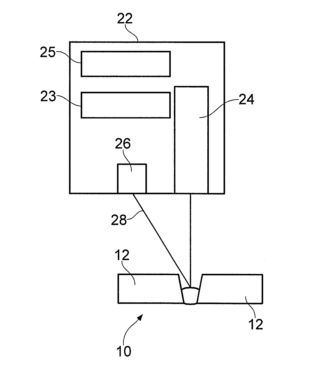
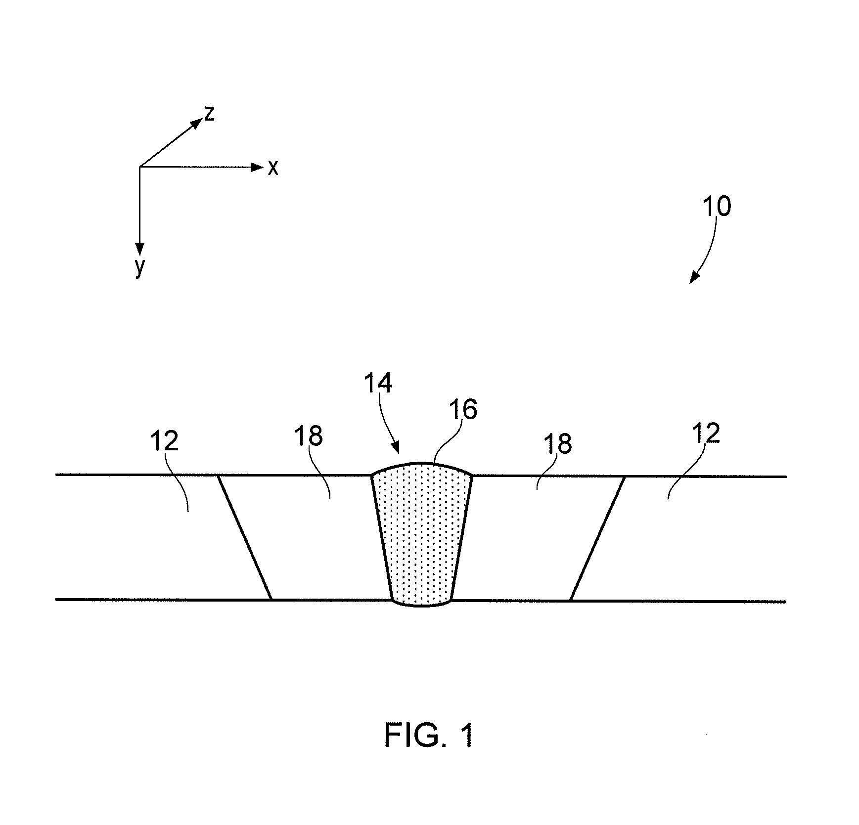
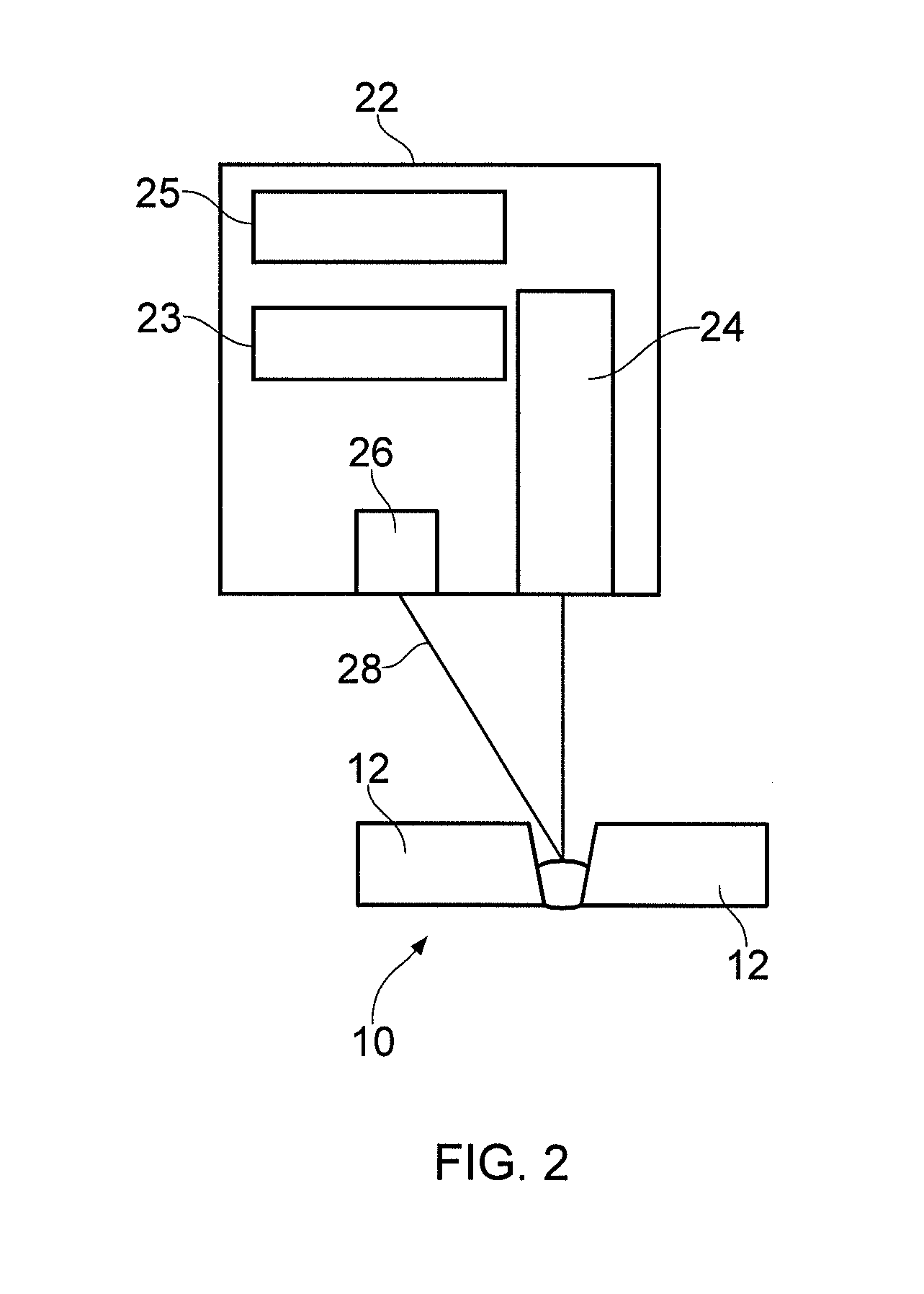
[0051]Many metallic structures in the nuclear industry are fabricated by welding metallic components together, for example reactor vessels. Given the environment the structures operate in, the components are often thick walled (for example a thick-walled pressure vessel may have a wall thickness equal to or greater than 200 mm, for example equal to or between 250 mm and 350 mm) and the weld needs to maintain its structural integrity under the hostile conditions of a nuclear power plant.

[0052]Methods for welding a component in the nuclear industry include arc welding, electron beam welding, or laser welding. In arc welding, an electric arc is created between an electrode and the components to be welded. In the nuclear industry, the electrode is generally consumable to provide a filler material for the weld. In electron beam welding a focussed stream of high energy electrons, and in laser beam welding a concentrated heat source, is used to melt the metal of the components to form the ...


PUM

PropertyMeasurementUnit
Temperatureaaaaaaaaaa
Electric potential / voltageaaaaaaaaaa
Heataaaaaaaaaa

Abstract

A method of welding two adjacent components together includes determining geometrical dimensions of the components to be welded and determining material properties of the components to be welded. The method includes selecting an optimised weld torch velocity and voltage by selecting an iteration parameter of weld torch velocity and voltage, and calculating an expected heat flux distribution that will be generated in components during a welding process as a function of the geometrical dimensions of the components and the material properties of the components. The heat flux distribution is constrained to be ellipsoidal in an initial weld region and conical in the remainder of the weld. The method includes iterating using the iteration parameter until an optimised weld torch velocity and voltage is obtained. The welding torch is then set to weld the components at the determined optimum velocity and voltage.

Description

TECHNICAL FIELD[0001]The present disclosure concerns a method of welding and / or apparatus used for welding.BACKGROUND[0002]Many structures and assemblies of a nuclear power plant are manufactured by welding large components together. The components are generally thick-walled components, for example 10 mm to 350 mm thick, designed to meet process and regulatory requirements for a nuclear power plant. Pressure vessels of a nuclear power plant often have a wall thickness greater than or equal to 200 mm. The welds of these thick walled components need to be designed to maintain component integrity during in-service conditions.[0003]To form the joint between thick-walled components, multiple weld passes may be required. A failure causing the welding process to stop part-way through the welding of components can result in the components being scraped.[0004]When the weld (often referred to as the weldment) between components cools a stress remains and the components are distorted from thei...

Claims


Application Information

Patent Timeline
IPC IPC(8): B23K9/095
CPCB23K9/095B23K9/0953B23K31/02B23K31/003B23K31/006B23K31/12
Inventor FLINT, THOMAS FERNLEY
Owner ROLLS ROYCE PLC
Why Eureka
Try Eureka