Supercharge Your Innovation With Domain-Expert AI Agents!

Bar movement control device of heading machine

A motion control device and heading machine technology, applied in manufacturing tools, other manufacturing equipment/tools, metal processing equipment, etc., can solve the problems of uneven friction, rotational offset of metal bars, bending of metal bars, etc. To achieve the effect of reducing the offset

Active Publication Date: 2021-06-11
济南恒鑫锻造有限公司
View PDF7 Cites 1 Cited by
  • Summary
  • Abstract
  • Description
  • Claims
  • Application Information

AI Technical Summary

Problems solved by technology

[0002] Heading machine is a processing equipment that beats the ends of metal bars at both ends to form protruding parts in order to facilitate the clamping of metal bars that need to be drawn. The head of metal bars needs to be beaten many times to complete. It is necessary for the header bar motion control device to control the rotation of the metal bar so that the metal bar can be rotated to ensure the balance of beating at both ends of the metal bar. In the process of processing metal bars for motion control, because the outer wall of rough-machined metal bars is generally accompanied by a small amount of rust, the friction force of the metal bar wall where the rust is attached is greater, making it easy to be driven by the rotating mechanism due to its outer wall. The unbalanced friction force everywhere causes the rotation of the metal bar to be offset, which in turn causes the metal bar to bend after the head is started

Method used


Image

  • Bar movement control device of heading machine
  • Bar movement control device of heading machine
  • Bar movement control device of heading machine

Examples


Embodiment 1

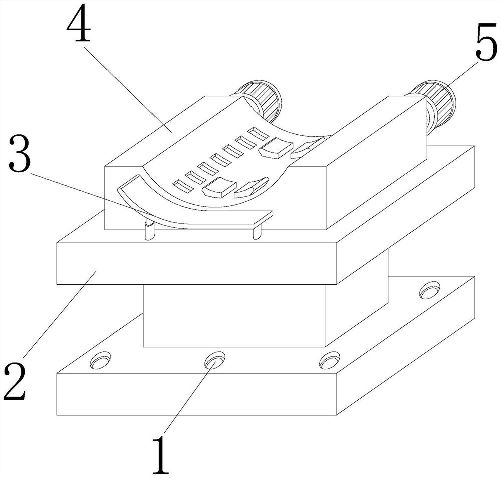
[0028] Such as Figure 1-Figure 6 As shown, the present invention provides a heading machine bar movement control device, its structure includes a connection hole 1, a mounting seat 2, a push plate 3, an engaging device 4, and a driver 5, and the connection hole 1 is opened at the lower end of the mounting seat 2 Around the surroundings, the bottom end of the push plate 3 is embedded and fixed at the front end of the upper part of the mounting base 2, the bottom end of the engaging device 4 is welded to the center of the upper surface of the mounting base 2, and the front end of the driver 5 is driven and matched to the engaging device 4 sides of the rear end.

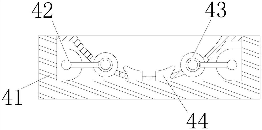
[0029] The engaging device 4 includes an outer cover 41, a torsion bar 42, a rotating device 43, and a receiving block 44. The side ends of the torsion bar 42 are embedded on both sides of the inner wall of the outer cover 41, and the front end of the rotating device 43 is hinged to the torsion bar 42. At the side end...

Embodiment 2

[0037] Such as Figure 7-Figure 8 Shown:

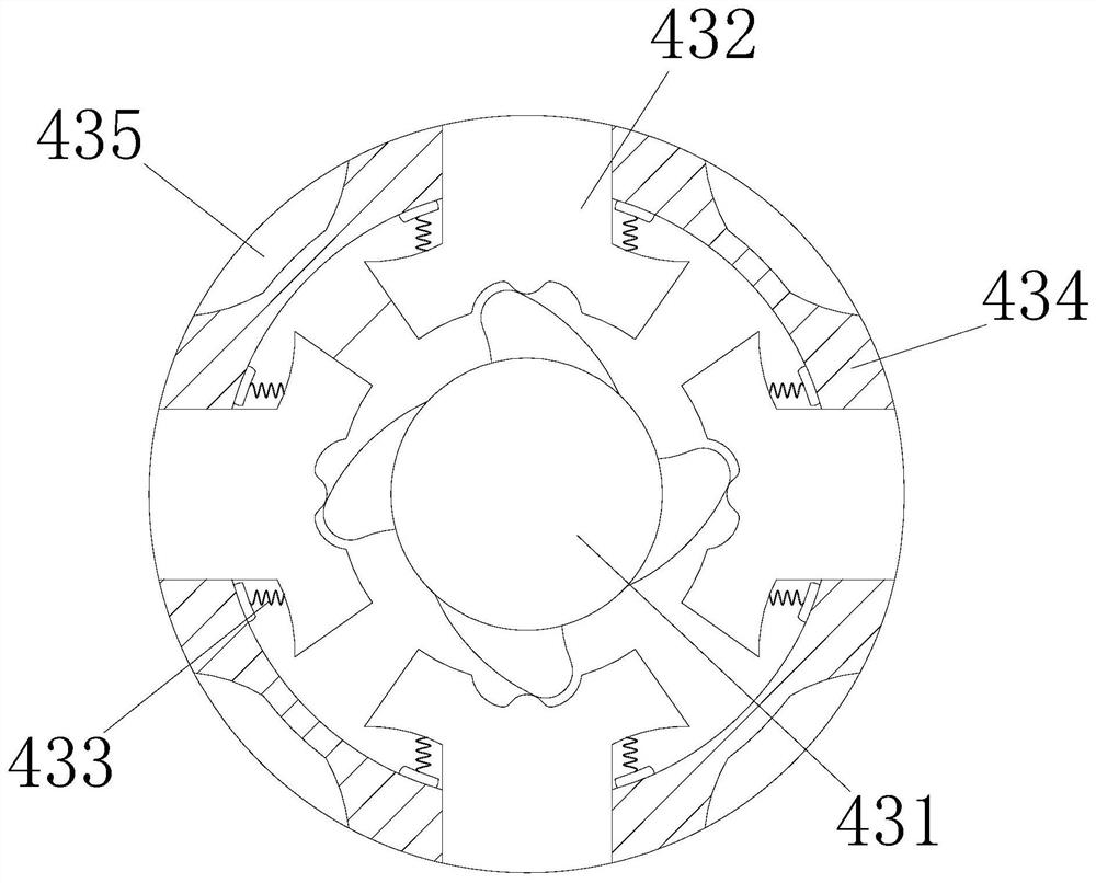
[0038] Wherein, the grinding mechanism 435 includes a fixed piece c1, an engaging piece c2, a chute c3, and a grinding block c4. The lower end wall of the engaging piece c2 is embedded and connected to the upper surface of the fixing piece c1. Inside the upper wall of the engaging piece c2, the bottom end of the grinding block c4 is embedded in the upper wall surface of the engaging piece c2, and the chute c3 is an inclined straight groove structure, which enables it to accommodate more More fallen rust, so as to prevent the rust from falling off and covering the surface of the grinding block c4, which will affect the subsequent grinding.

[0039] Wherein, the grinding block c4 includes a bottom plate c41, an upper cover c42, a grinding ball c43, and a cone c44. Connected to the upper end wall surface of the upper cover c42, the lower end of the cone block c44 is embedded and connected to both sides of the upper wall surface of the ...


PUM


Abstract

The invention discloses a bar movement control device of heading machine. The bar movement control device structurally comprises connecting holes, a mounting seat, a pushing plate, a clamping device and a driver, the connecting holes are formed in the periphery of the lower end of the mounting seat, the bottom end of the pushing plate is fixedly embedded in the front end of the upper portion of the mounting seat, the bottom end of the clamping device is welded to the center of the surface of the upper end of the mounting seat, and the front end of the driver is driven to be matched with the two sides of the rear end of the clamping device. According to the bar movement control device, after rust on the outer wall of a metal bar affects rotation of a shell, a flywheel continues to rotate due to inertia, rotation of the flywheel extrudes a telescopic mechanism, the telescopic mechanism protrudes outwards under elastic connection of a spring, a sliding block is extruded outwards, a sliding mechanism of the extruded sliding block is in contact with the bar, due to the fact that balls in the sliding mechanism are in incomplete contact magnetic connection with a clamping ring, the extremely low friction force enables the metal bar to rotate more smoothly, and then the offset generated in the rotating process is reduced.

Description

technical field [0001] The invention relates to the field of motion control, in particular to a motion control device for a heading machine bar. Background technique [0002] Heading machine is a processing equipment that beats the ends of metal bars at both ends to form protruding parts in order to facilitate the clamping of metal bars that need to be drawn. The head of metal bars needs to be beaten many times to complete. It is necessary for the header bar motion control device to control the rotation of the metal bar so that the metal bar can be rotated to ensure the balance of beating at both ends of the metal bar. In the process of processing metal bars for motion control, because the outer wall of rough-machined metal bars is generally accompanied by a small amount of rust, the friction force of the metal bar wall where the rust is attached is greater, making it easy to be driven by the rotating mechanism due to its outer wall. The unbalanced friction force everywhere...

Claims


Application Information

Patent Timeline
Patent Type & Authority Applications(China)
IPC IPC(8): B23P23/04B21C5/00B24B27/033
CPCB23P23/04B21C5/006B24B27/033
Inventor 方莉
Owner 济南恒鑫锻造有限公司
Features
  • R&D
  • Intellectual Property
  • Life Sciences
  • Materials
  • Tech Scout
  • Unparalleled Data Quality
  • Higher Quality Content
  • 60% Fewer Hallucinations
Learn More