Rapid cooling device for injection mold

A rapid cooling, injection mold technology, applied in the field of mold cooling, can solve the problems of low production efficiency, difficult heat dissipation of injection molds, slow product curing, etc., to speed up water cooling efficiency, avoid worker burns, and increase the effect of contact area.

Pending Publication Date: 2021-06-11
厦门钰得沣塑胶有限公司
View PDF0 Cites 0 Cited by
  • Summary
  • Abstract
  • Description
  • Claims
  • Application Information

AI Technical Summary

Problems solved by technology

[0002] Injection molding is a tool for producing plastic products; it is also a tool for giving plastic products a complete structure and precise dimensions. Injection molding is a processing method used in mass production of certain complex-shaped parts; The injection molding machine injects high pressure into the mold cavity, and after cooling and solidification, the molded product is obtained. In the process of using injection mold processing, multiple molds are often required to cool down so that the injection molded product can be solidified quickly, thereby improving the production efficiency of the product, but The existing cooling devices for injection molds have the following problems: most of the existing injection molds are thick and heavy, and the heat dissipation effect is too poor, which makes it difficult to dissipate the heat inside the injection mold, and then the heat dissipation of the legal injection mold is slow. Most of the heat dissipation methods are wind blowing, which is often difficult to dissipate the heat inside the injection mold, which leads to slow product solidification, low product production efficiency, and a large amount of heat will be emitted during cooling, which may easily cause burns to workers , has certain limitations, therefore, it is necessary to design a rapid cooling device for injection molds to solve the above problems

Method used


Image

  • Rapid cooling device for injection mold
  • Rapid cooling device for injection mold
  • Rapid cooling device for injection mold

Examples


Embodiment

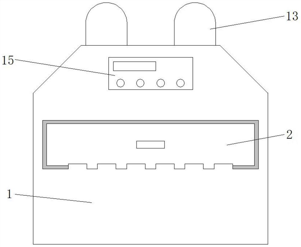
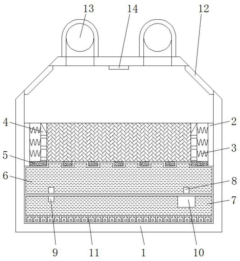
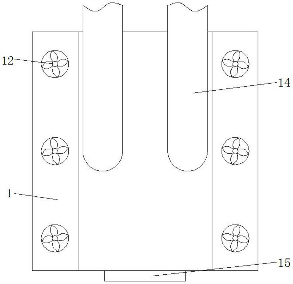
[0019] Example: refer to Figure 1-3 , a rapid cooling device for injection molds, including a casing 1, a storage cabinet 2 is slidably connected to the casing 1, and several springs 3 are connected to the inner walls of the two ends of the storage cabinet 2, and one end of the spring 3 is connected to and installed with The fixed plate 4, the bottom of the storage cabinet 2 is provided with a heat conducting plate 5, and the bottom of the heat conducting plate 5 is provided with a circulating water tank 6, the bottom of the circulating water tank 6 is provided with a cooling tank 7, and a water inlet pipe 8 is connected between the circulating water tank 6 and the cooling tank 7 And the drain pipe 9, the water inlet pipe 8 is connected to the water pump 10 through the cooling box 7, the inner wall of the bottom of the cooling box 7 is laid with a condensing plate 11, the two sides of the casing 1 are connected and installed with several exhaust fans 12, and the top of the cas...


PUM


Abstract

The invention relates to the technical field of mold cooling, in particular to a rapid cooling device for an injection mold. The rapid cooling device comprises a machine shell, wherein a placement cabinet is slidably connected in the machine shell, a plurality of springs are connected on the inner walls of the two ends of the placement cabinet, and a fixing plate is connected to one end of each spring; a heat conducting plate is arranged at the bottom of the placement cabinet, and a circulating water tank is arranged at the bottom of the heat conducting plate; a cooling tank is arranged at the bottom of the circulating water tank, and a water inlet pipe and a water drainage pipe are connected between the circulating water tank and the cooling tank; a water pump is connected to the water inlet pipe through the cooling tank, and a condensation plate is laid on the inner wall of the bottom of the cooling tank; a plurality of exhaust fans are connected to the two sides of the machine shell, and an exhaust pipe is fixedly connected to the top end of the machine shell; and a control panel is fixedly arranged on one side of the machine shell. The rapid cooling device can achieve rapid cooling, can effectively prevent personnel from being scalded, and has certain practicability.

Description

technical field [0001] The invention relates to the technical field of mold cooling, in particular to a rapid cooling device for injection molds. Background technique [0002] Injection molding is a tool for producing plastic products; it is also a tool for giving plastic products a complete structure and precise dimensions. Injection molding is a processing method used in mass production of certain complex-shaped parts; The injection molding machine injects high pressure into the mold cavity, and after cooling and solidification, the molded product is obtained. In the process of using injection mold processing, multiple molds are often required to cool down so that the injection molded product can be solidified quickly, thereby improving the production efficiency of the product, but The existing cooling devices for injection molds have the following problems: most of the existing injection molds are thick and heavy, and the heat dissipation effect is too poor, which makes i...

Claims


Application Information

Patent Timeline
Patent Type & Authority Applications(China)
IPC IPC(8): B29C45/73
CPCB29C45/7312B29C45/7337
Inventor 洪丽蓉
Owner 厦门钰得沣塑胶有限公司
Why Eureka
Try Eureka