Carton manufacturing process
A manufacturing process and carton technology, which is applied in the field of carton processing, can solve the problems of inability to process carton boxes, and achieve the effects of easy classification, increased compressive capacity and strength
- Summary
- Abstract
- Description
- Claims
- Application Information
AI Technical Summary
Problems solved by technology
Method used
Image
Examples
specific Embodiment approach 1
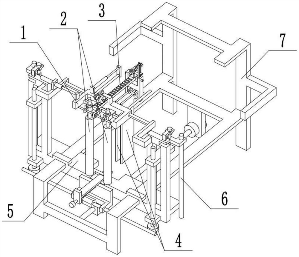
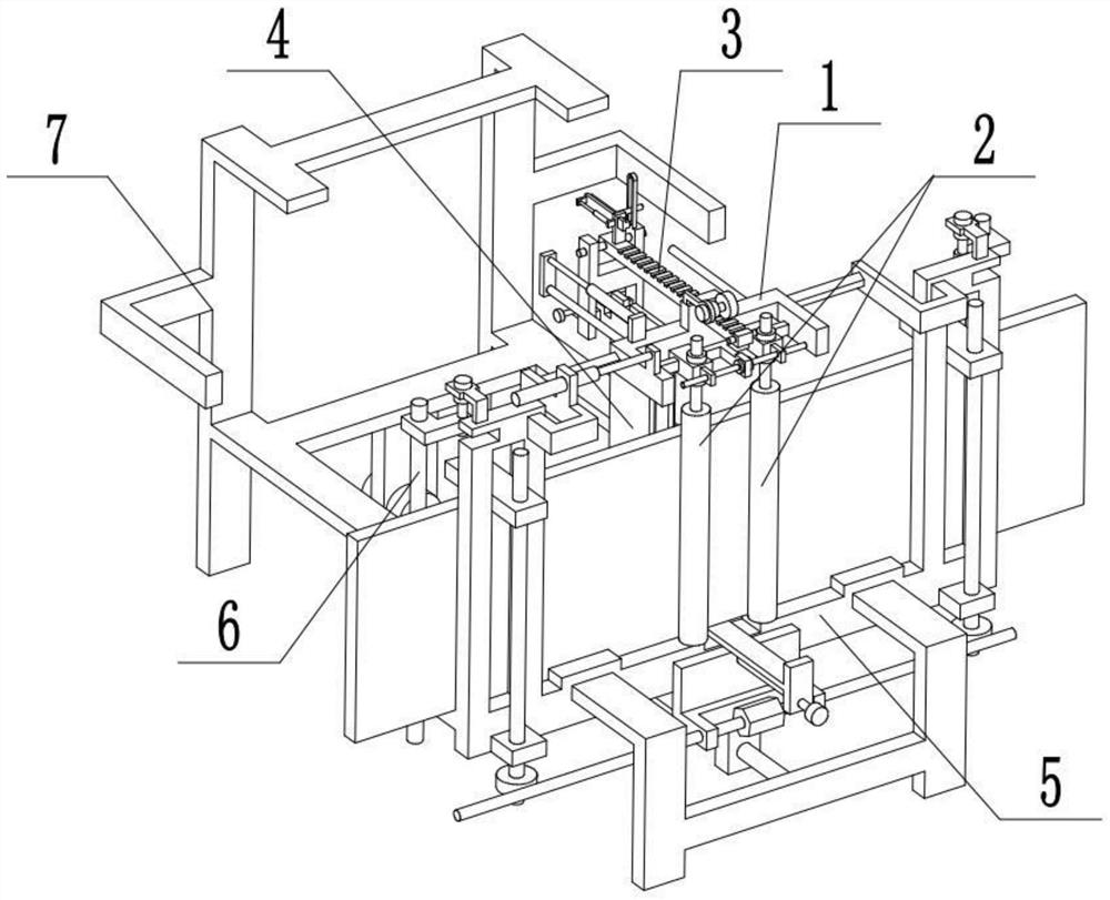
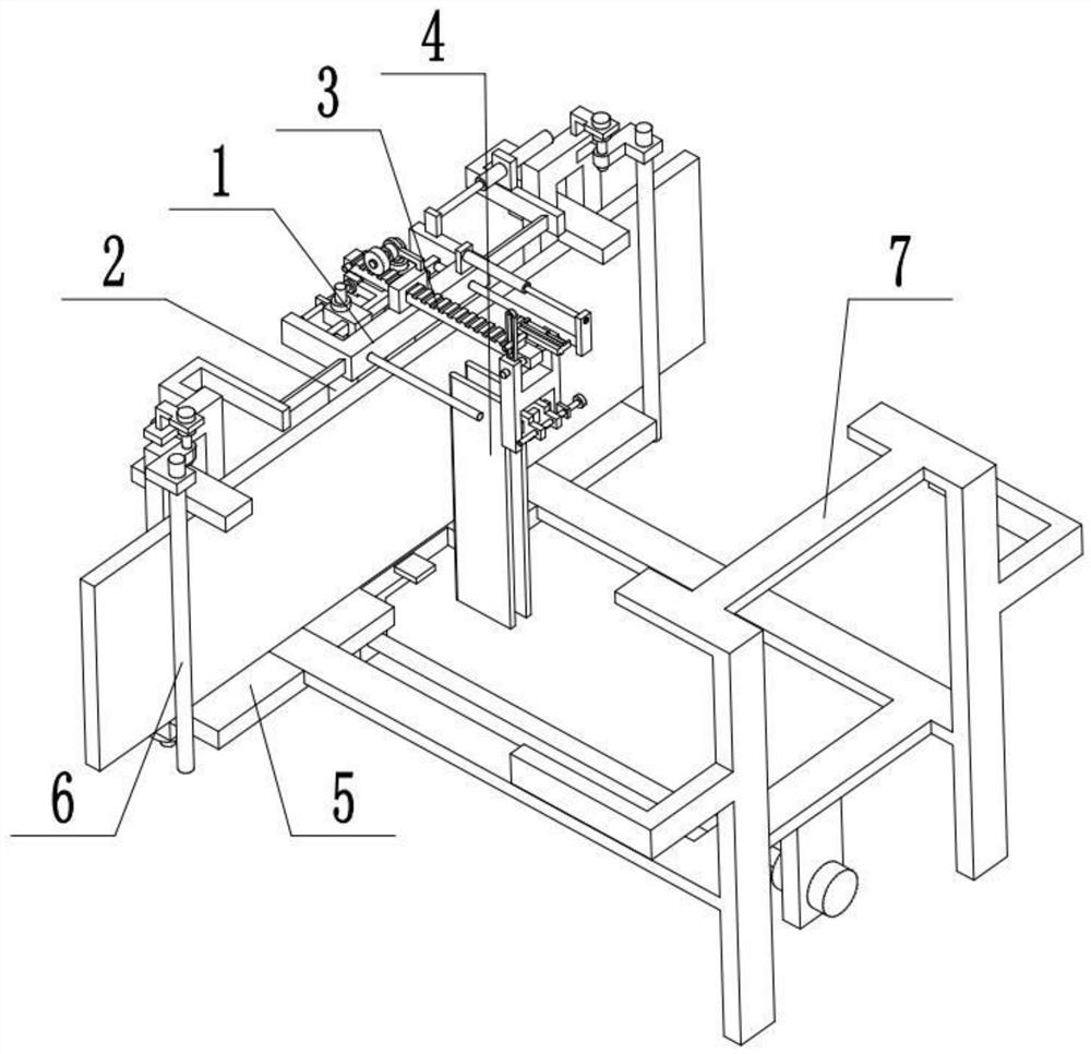
[0038] Combine below Figure 1-10 To illustrate this embodiment, a carton manufacturing process includes the following steps:
[0039] Step 1. Place the cardboard core board;
[0040] Step 2. Press the core board of the paper shell out of the ribs;
[0041] Step 3. Take out the paper shell core board and cover it with glue;
[0042] Step 4. Paste the cardboard core board into the placed carton box;
[0043] The above carton manufacturing process also involves a carton manufacturing device;
[0044]The carton manufacturing device includes a U-shaped seat 1, a motor 1-4, a gear 1-5, a pressure roller 2, a rack 3, a pressing plate 4, an H-shaped frame 4-1 and a base 5, and the U-shaped seat 1 is arranged on the base 5, two pressure rollers 2 are arranged on the U-shaped seat 1, the motor one 1-4 is fixedly connected on the U-shaped seat 1, the output shaft of the motor one 1-4 is fixedly connected with the gear 1-5, and the gear 1-5 is connected with the gear The bar 3 is me...
specific Embodiment approach 2
[0046] Combine below Figure 1-10 To illustrate this embodiment, the carton manufacturing process also includes a rotating shaft 3-1, a vertical plate 3-2, a T-shaped plate 3-3, a driving rod 3-4, an oil cylinder 3-5 and a groove plate 4-4, The rotating shaft 3-1 is fixedly connected to the H-shaped frame 4-1, the rack 3 is rotationally connected to the rotating shaft 3-1, the vertical plate 3-2 is fixedly connected to the rack 3, the T-shaped plate 3-3 is connected to the vertical plate 3- 2 sliding connection, the right end of the T-shaped plate 3-3 is fixedly connected to the driving rod 3-4, the driving rod 3-4 is slidingly connected in the slot plate 4-4, and the slot plate 4-4 is fixedly connected to the H-shaped frame 4-1 , Oil cylinder three 3-5 is fixedly connected on the vertical plate 3-2, and the telescoping end of oil cylinder three 3-5 is fixedly connected at the rear end of T-shaped plate 3-3. When it is necessary to take out the core board of the paper shell, ...
specific Embodiment approach 3
[0048] Combine below Figure 1-10 To illustrate this embodiment, the carton manufacturing process also includes a square rod 4-2, a bidirectional threaded rod 4-3, a T-shaped frame 2-1, a biaxial motor 2-2, a lead screw 2-3, and a slider 2-4 and the vertical shaft 2-5, the square rod 4-2 is fixedly connected to the lower end of the H-shaped frame 4-1, the two pressure plates 4 are all slidably connected to the square rod 4-2, and the two-way threaded rod 4-3 is rotatably connected On the H-shaped frame 4-1, the rear ends of the two pressure plates 4 are threaded symmetrically at the two ends of the bidirectional threaded rod 4-3; The output shafts at both ends of the motor 2-2 are respectively fixedly connected to a lead screw 2-3, and the two slide blocks 2-4 are respectively threaded with the two lead screw 2-3, and the two slide blocks 2-4 are respectively movably connected to the The two ends of the T-shaped frame 2-1 are respectively rotatably connected to a vertical sha...
PUM
 Abstract
Description
Claims
Application Information
 - R&D
- Intellectual Property
- Life Sciences
- Materials
- Tech Scout
- Unparalleled Data Quality
- Higher Quality Content
- 60% Fewer Hallucinations
Browse by: Latest US Patents, China's latest patents, Technical Efficacy Thesaurus, Application Domain, Technology Topic, Popular Technical Reports.
© 2025 PatSnap. All rights reserved.Legal|Privacy policy|Modern Slavery Act Transparency Statement|Sitemap|About US| Contact US: help@patsnap.com


