Hollow casting type rubber bushing assembly

A technology of rubber bushings and castings, applied to vehicle parts, cantilevers mounted on pivots, suspensions, etc., can solve the problem that the self-weight of the steel inner core is not reduced, and the rear shock-absorbing rubber bushing assembly is lightweight. Insignificant and other problems, to achieve the effect of reducing overall weight, reducing production processes, and reducing self-weight

Inactive Publication Date: 2021-06-11
长岛高能聚氨酯有限公司
View PDF6 Cites 0 Cited by
  • Summary
  • Abstract
  • Description
  • Claims
  • Application Information

AI Technical Summary

Problems solved by technology

[0004] In view of the above-mentioned related technologies, the inventor believes that although the above-mentioned rear shock-absorbing rubber bush assembly can reduce its own weight to a certain extent, the steel inner core is a solid structure, so that the self-weight of the steel inner core has not been reduced, resulting in The overall weight reduction effect of the above-mentioned rear shock-absorbing rubber bushing assembly is not significant

Method used


Image

  • Hollow casting type rubber bushing assembly
  • Hollow casting type rubber bushing assembly
  • Hollow casting type rubber bushing assembly

Examples


Embodiment 1

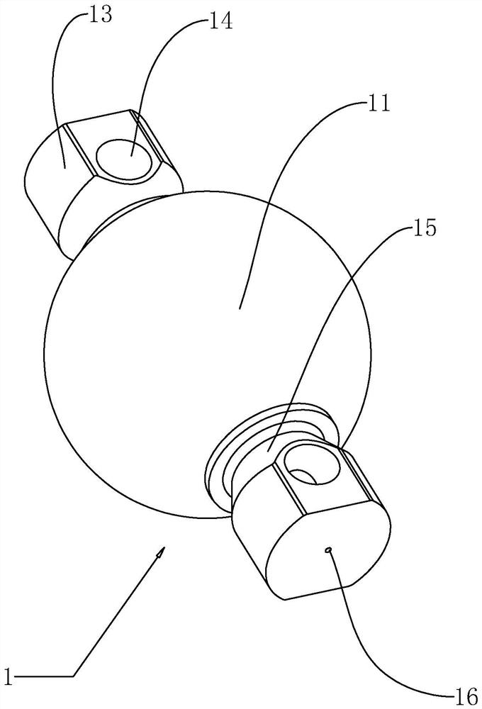
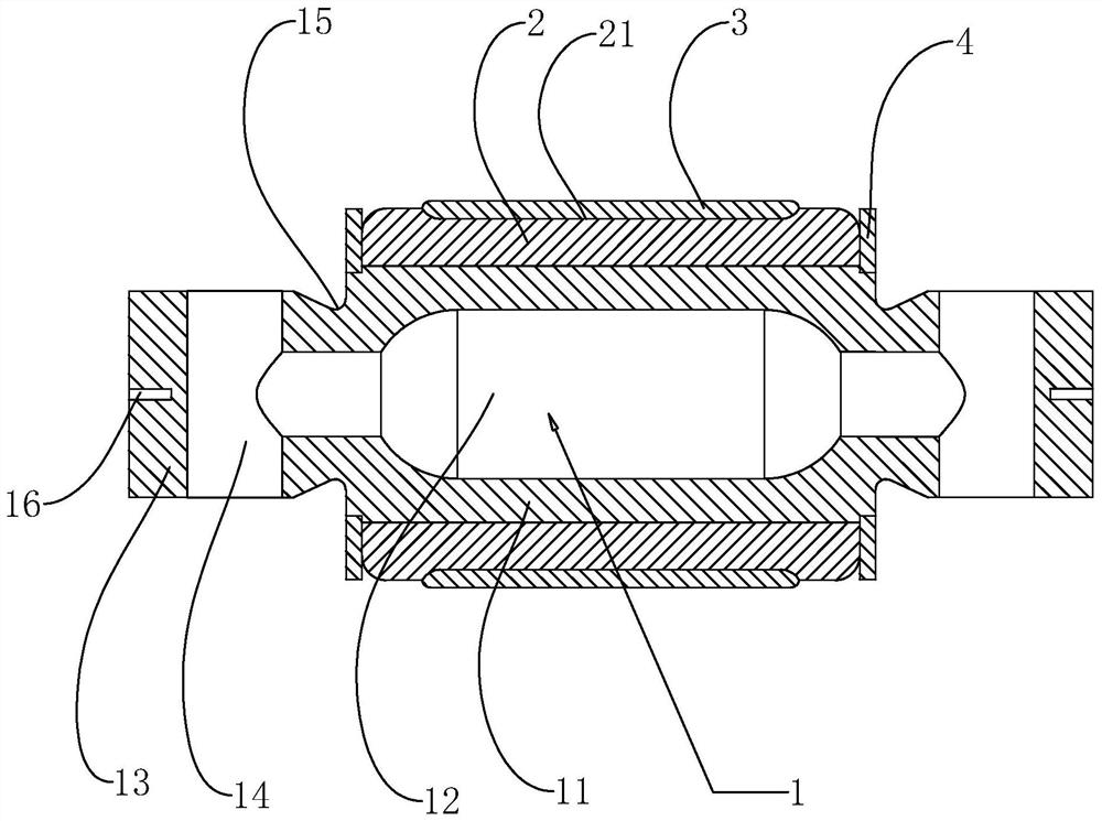
[0039] refer to figure 1 and figure 2 , a hollow casting type rubber bushing assembly, including the joint ball pin 1, the joint ball pin 1 is made of rubber material as a whole, and the rubber material is elastic and deformable. The joint ball pin 1 includes a ball pin body 11. The ball pin body 11 has a spherical structure without external force. The ball pin body 11 is provided with a hollow cavity 12, and the central cavity is placed at the center of the ball pin body 11. . Through the arrangement of the hollow cavity 12, the dead weight of the ball pin body 11 is greatly reduced, and the weight reduction effect is realized.

[0040] refer to figure 1 , the two ends of the ball pin body 11 are integrally connected with ball pin ends 13 respectively, the two ball pin ends 13 and the ball pin body 11 are on the same linear position, and the shape and size of the ball pin ends 13 are smaller than the ball pin body 11 shape and size. The ball pin end 13 is provided with ...

Embodiment 2

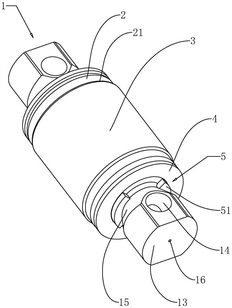
[0053] refer to figure 2 and Figure 4 The difference between the second embodiment and the first embodiment lies in the difference of the limit mechanism 5, the limit mechanism 5 includes a snap spring 52, the inner diameter of the snap spring 52 is smaller than the inner diameter of the end cover 4, and the operator uses the snap spring 52 to clamp and other related circlip 52 installation tools, the circlip 52 is installed between the end cover 4 and the ball pin body 11, so that the circlip 52 is placed in the rotation groove 15, and the end face of the circlip 52 is directly close to the ball pin body 11. The end surface of the pin end 13 is connected against each other, and the ball pin body 11 is further limited between the two end caps 4 through the cooperation of the end cover 4 and the snap spring 52, and finally the rotation of the ball pin body 11 in the bushing shell 2 is improved. stability.

[0054] The implementation principle of the second embodiment of the...


PUM


Abstract

The invention relates to a hollow casting type rubber bushing assembly which comprises a joint ball pin, the joint ball pin comprises a ball pin body, the two ends of the ball pin body are integrally connected with ball pin ends correspondingly, connecting holes penetrating through the ball pin ends are formed in the ball pin ends, a hollow cavity is formed in the ball pin body, the two ends of the hollow cavity communicate with the connecting holes correspondingly, and the outer side of the ball pin body is sleeved with a lining shell. An operator firstly pulls the two ends of the end portion of the ball pin, stretches the two ends of the end portion of the ball pin and extrudes the ball pin body at the same time, the ball pin body is directly installed in the lining shell, the use frequency of an adhesive is reduced in the production process, therefore, independent components are independently produced, then the components are assembled through stretching and extruding methods, and the production procedures are reduced. Through communication between the hollow cavity and the connecting hole, the hollow casting process of the rubber joint ball pin is achieved through sand core casting, the self weight of the whole joint ball pin is reduced, and the effect that the whole lining assembly is light in weight is remarkably achieved.

Description

technical field [0001] The present application relates to the field of rubber bushing assemblies, in particular to a hollow casting type rubber bushing assembly. Background technique [0002] Automotive thrust rod rubber bushing assembly, also known as thrust rod rubber ball hinge and torsion rubber core, is the core connecting part for the frame, axle and balance suspension. Its main functions are shock absorption, rotation and torsion and connection . [0003] The existing Chinese patent with the notification number CN207814292U discloses a rear shock-absorbing rubber bushing assembly, which includes a longitudinally long inner core with connecting holes at both ends, and a cylindrical plastic layer overlaid on the inner core. The plastic layer is covered with a cylindrical rubber body, and the rubber body is covered with a metal outer tube. [0004] In view of the above-mentioned related technologies, the inventor believes that although the above-mentioned rear shock-ab...

Claims


Application Information

Patent Timeline
Patent Type & Authority Applications(China)
IPC IPC(8): B60G7/00B60G7/04
CPCB60G7/005B60G7/04
Inventor 于海琳季禄顺庞龙孙维安
Owner 长岛高能聚氨酯有限公司
Why Eureka
Try Eureka