
Low-orbit satellite two-degree-of-freedom solar wing control method

A degree of freedom, low-orbit technology, applied in space navigation equipment, space navigation equipment, transportation and packaging, etc., can solve the uncertainty of satellite attitude control system, the inability of solar wings to obtain energy, and the interruption of satellite work process. , to reduce the coupling effect, ensure the stability of the attitude, and reduce the management cost.

Active Publication Date: 2021-06-11
航天科工空间工程发展有限公司
View PDF5 Cites 1 Cited by
  • Summary
  • Abstract
  • Description
  • Claims
  • Application Information

AI Technical Summary

Problems solved by technology

[0003] Low-orbit broadband satellites need to adopt non-sun-synchronous orbits, resulting in periodic and large-scale changes in the angle between the sun and the orbital plane. When the sun shines on the orbital plane vertically, the solar wings on the vertical orbital plane cannot obtain energy
Therefore, if a satellite in a non-sun-synchronous orbit is only equipped with a single-degree-of-freedom solar wing, in order to realize the solar wing's orientation to the sun, the satellite needs to perform periodic large-angle attitude maneuvers, which will cause the satellite's working process to be periodically interrupted, and The periodic attitude maneuver of the satellite destroys the existing attitude stability. After the maneuver is completed, the stable attitude needs to be re-established, which will also bring the risk of uncertainty to the satellite attitude control system.

Method used


Image

  • Low-orbit satellite two-degree-of-freedom solar wing control method
  • Low-orbit satellite two-degree-of-freedom solar wing control method
  • Low-orbit satellite two-degree-of-freedom solar wing control method

Examples


Embodiment Construction

[0038] In order to make the technical solutions and advantages of the present invention clearer, the implementation manners of the present invention will be further described in detail below in conjunction with the accompanying drawings.

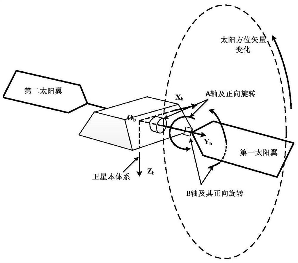
[0039] Such as figure 1 As shown, a structure diagram of a low-orbit satellite dual-degree-of-freedom solar wing, the solar wing refers to the solar wing in the ±Y-axis direction of the satellite system, and is defined as the first solar wing and the second solar wing respectively, and the double-freedom degree refers to the solar wing with two degrees of freedom of rotation and swing, the axis of rotation and the axis of swing are respectively figure 1 A-axis and B-axis. The rotation axis is consistent with the rotation axis of the single-degree-of-freedom solar wing; the swing axis is located on the extension rod of the output shaft of the rotation axis, and the rotation axis can drive the swing axis to rotate together, and the rotation d...


PUM


Abstract

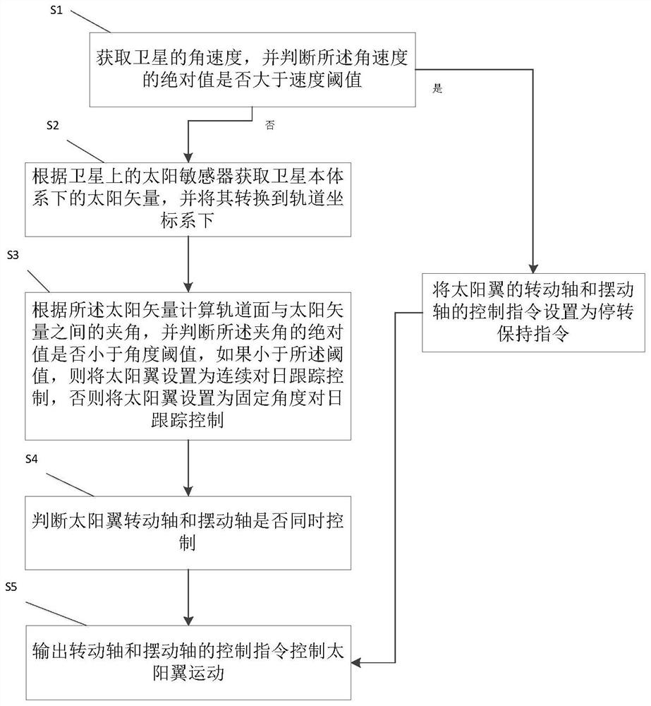
The embodiment of the invention discloses a low-orbit satellite two-degree-of-freedom solar wing control method, which comprises the following steps: S1, acquiring the angular velocity of a satellite, judging whether the absolute value of the angular velocity is greater than a velocity threshold value, if yes, setting a control instruction of a rotating shaft and a swinging shaft of a solar wing as a stalling keeping instruction, and then performing S5, otherwise, performing S2; S2, acquiring a sun vector in a satellite body system, and converting the sun vector into an orbital coordinate system; S3, calculating an included angle between the orbital plane and the sun vector, judging whether the absolute value of the included angle is smaller than an angle threshold value or not, if so, setting the solar wing as continuous sun tracking control, and otherwise, setting the solar wing as fixed-angle sun tracking control; S4, judging whether the rotating shaft and the swinging shaft of the solar wing are controlled at the same time, if yes, executing S5, and otherwise, adjusting the instruction of the rotating shaft; and S5, outputting control instructions of the rotating shaft and the swinging shaft to control the solar wing to move.

Description

technical field [0001] The invention relates to the technical field of spacecraft control. More specifically, it relates to a method for controlling a two-degree-of-freedom solar wing of a low-orbit satellite. Background technique [0002] Internet access anytime, anywhere is the most important feature of the current information age. Many foreign companies such as OneWeb and SpaceX have proposed large-scale low-orbit broadband satellite constellation systems, planning to provide Internet access services anytime, anywhere for the world. [0003] Low-orbit broadband satellites need to adopt non-sun-synchronous orbits, resulting in periodic and large-scale changes in the angle between the sun and the orbital plane. When the sun shines on the orbital plane vertically, the solar wings on the vertical orbital plane cannot obtain energy. Therefore, if a satellite in a non-sun-synchronous orbit is only equipped with a single-degree-of-freedom solar wing, in order to realize the sol...

Claims


Application Information

Patent Timeline
IPC IPC(8): B64G1/24B64G1/44
CPCB64G1/244B64G1/44
Inventor 金震辛星黄丽雅王鹏飞程春晓翟峻仪任涛
Owner 航天科工空间工程发展有限公司
Learn More