Foundation pit supporting equipment for geotechnical engineering

A technology for foundation pit support and geotechnical engineering, applied in mining equipment, infrastructure engineering, earthwork drilling and mining, etc., can solve problems such as uneven mortar circulation, port damage, edge collapse, and cavity leakage, and achieve Guarantee the strength of support reinforcement, avoid bruising and edge collapse, and improve the effect of grouting efficiency

Active Publication Date: 2021-12-07
CHUZHOU UNIV
View PDF6 Cites 0 Cited by
  • Summary
  • Abstract
  • Description
  • Claims
  • Application Information

AI Technical Summary

Problems solved by technology

[0003] However, during the long-term use, it is found that the existing grouting equipment still has certain disadvantages: 1. Due to the complex stratum conditions, there will be faults and cracks inside, if the calibration position is just at the position corresponding to the faults , it will cause the mortar to be lost into the fault during the grouting process, and the amount of grout to fill all the fault fissures will be quite large, and if the grouting space is too large, the rapid-setting expansion grout will be filled unevenly in the hole And leakage cavities appear, which affects the strength of support and reinforcement; 2. During the grouting process, there are various drilling angles of the grouting hole in the deep foundation pit of the tunnel, and a stable relationship between the anchor rod and the outer wall of the grouting hole cannot be guaranteed. Verticality, resulting in uneven flow of mortar in the grouting hole, and non-parallel insertion with the grouting hole will easily lead to damage and collapse of the port part

Method used


Image

  • Foundation pit supporting equipment for geotechnical engineering
  • Foundation pit supporting equipment for geotechnical engineering
  • Foundation pit supporting equipment for geotechnical engineering

Examples


Embodiment Construction

[0024] In order to make the technical means, creative features, goals and effects achieved by the present invention easy to understand, the present invention will be further described below in conjunction with specific embodiments.

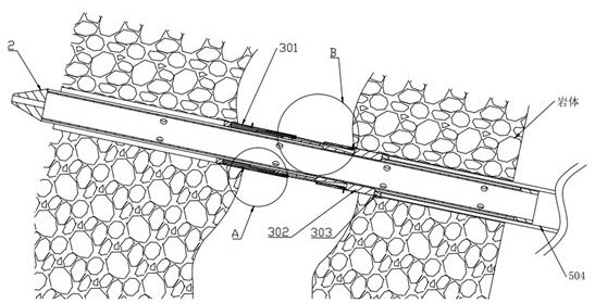
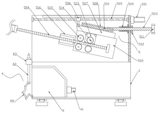
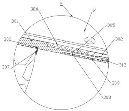
[0025] Such as Figure 1 to Figure 6 As shown, a foundation pit support equipment for geotechnical engineering includes a trolley 1, an anchor rod 2, a partition 3, a grouting mechanism 4, and an adjustment mechanism 5. A grout storage chamber 6 is arranged inside the trolley 1, The grouting mechanism 4 is installed on the grout storage chamber 6, and is used for injecting mortar into the rock mass drilling, and the adjusting mechanism 5 is installed in the trolley 1, and is used for adjusting the entry angle of the bolt 2, The partition 3 is sheathed on the anchor rod 2, and is used to prevent the slurry from spreading in the cracks of rock faults.

[0026] In this embodiment, the reinforcing grout used is a fluid mortar, and an accelerator and ...


PUM


Abstract

The invention discloses foundation pit support equipment for geotechnical engineering, relates to the technical field of geotechnical engineering, and comprises a trolley, a bolt, a partition, a grouting mechanism and an adjustment mechanism, and a grout storage chamber is arranged inside the trolley . The present invention prevents the grout from flowing and diffusing on the bolt by setting a partition on the bolt, and can realize effective grouting for fault fissures of any size, greatly reducing the required grout consumption; The adjustment mechanism is set to realize the adjustment and rotation of the push rod at any angle from horizontal to vertical by the rotating seat, and the fluid mortar can effectively flow out from all the grouting holes, which improves the grouting efficiency and ensures that the anchor rod and the outer wall of the grouting hole The verticality between them avoids the consequences of bruising and edge collapse on the port part, and further ensures the reinforcement strength of the support; it can also realize the purpose that the rod can be kept parallel to the rock mass drilling under any construction environment, and is suitable for Stronger.

Description

technical field [0001] The invention relates to the technical field of geotechnical engineering, in particular to foundation pit supporting equipment for geotechnical engineering. Background technique [0002] The excavation and support of the deep foundation pit of the tunnel refers to the support of the cap platform through the analysis of the surrounding conditions. It is a measure of support, reinforcement and protection for the construction of the deep rock foundation underground structure and the surrounding environment. , usually the calibration position is drilled by a rock drilling machine, and then the fluid mortar is injected into the hole through the anchor rod, and the slurry is diffused and consolidated in the hole to effectively improve the stability of the support structure. [0003] However, during the long-term use, it is found that the existing grouting equipment still has certain disadvantages: 1. Due to the complex stratum conditions, there will be fault...

Claims


Application Information

Patent Timeline
Patent Type & Authority Patents(China)
IPC IPC(8): E21D21/00E02D17/04
CPCE02D17/04
Inventor 李孝雄邸云菲杨兴振郭振宇胡明华
Owner CHUZHOU UNIV
Why Eureka
Try Eureka