Eureka AIR delivers breakthrough ideas for toughest innovation challenges, trusted by R&D personnel around the world.

Hot air knife

An air knife and hot air technology, applied in the field of machinery, can solve problems such as increasing power consumption, increasing electric heating power, and heat energy loss, and achieves the effects of improving thermal efficiency, increasing flow rate, and reducing energy consumption

Pending Publication Date: 2021-06-11
XUZHOU NORMAL UNIVERSITY
View PDF0 Cites 0 Cited by
  • Summary
  • Abstract
  • Description
  • Claims
  • Application Information

AI Technical Summary

Problems solved by technology

During the use of the existing hot air knife, because its heating part is at the air source, when the hot air reaches the air outlet of the hot air knife, and because the length of the air knife is relatively long, the hot air flow guided in the hot air duct will pass through There is a phenomenon of temperature drop on the surface of the air knife, and there is a certain loss of heat energy. If you want to achieve a higher temperature, you need to increase the electric heating power and increase the power consumption.

Method used


Image

  • Hot air knife
  • Hot air knife
  • Hot air knife

Examples


Embodiment

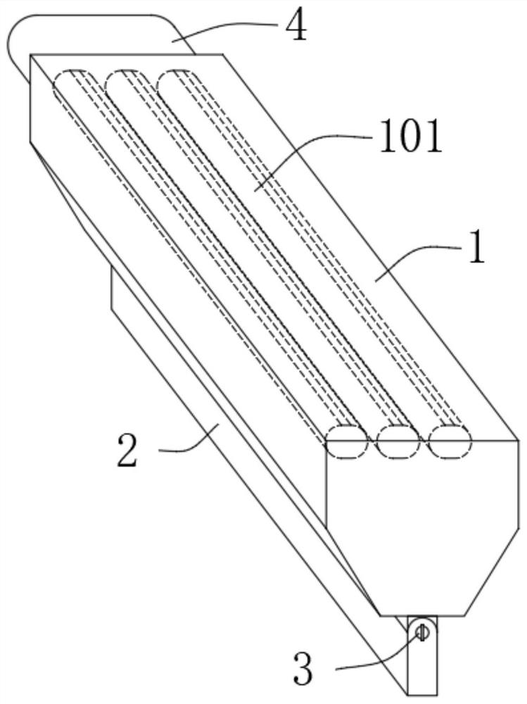
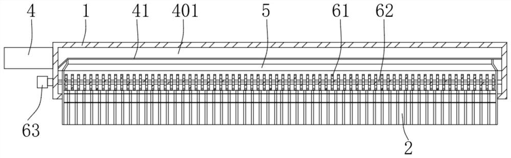
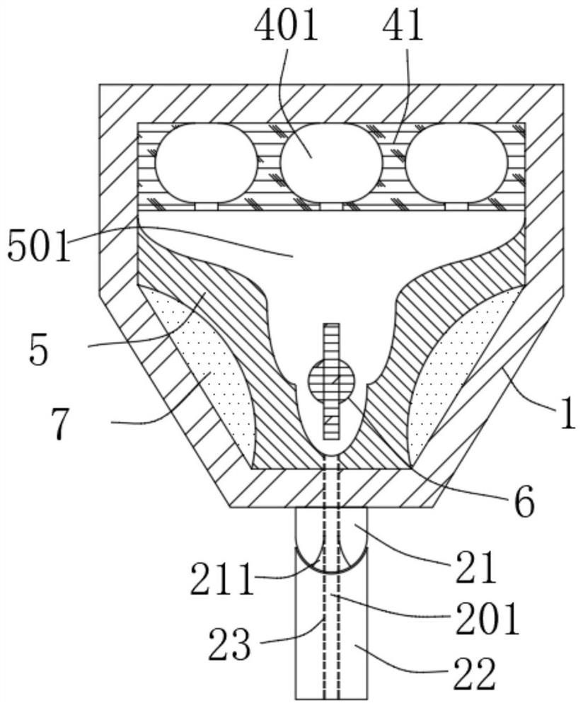
[0021] to combine Figure 1-3 As shown, the hot air knife includes an air knife shell 1 and an air outlet plate 2 arranged at the bottom of the air knife shell 1. One end of the air knife shell 1 is fixedly provided with an air inlet pipe 4 connected to an external air source. A heating mechanism 6 for heating the air flow is arranged on the inside corresponding to the top of the air outlet plate 2 , and the heating mechanism 6 is arranged along the length direction of the air knife housing 1 .

[0022] Among them, the air knife shell 1, the air outlet plate 2 and the air inlet pipe 4 can all be made of metal alloy materials. The cross section of the air knife shell 1 is an inverted trapezoidal structure, and the air outlet plate 2 is arranged at the bottom of the air knife shell 1, which is beneficial to the compressed air flow. The air outlet plate 2 leads out, and the heating mechanism 6 can adopt an electric heating wire, so that the airflow is heated when passing through ...


PUM


Abstract

A hot air knife comprises an air knife shell and an air outlet plate arranged at the bottom of the air knife shell, an air inlet pipe connected with an external air source is fixedly arranged at one end of the air knife shell, a heating mechanism used for heating airflow is arranged in the position, corresponding to the upper side of the air outlet plate, in the air knife shell, and the heating mechanism is arranged in the length direction of the air knife shell. The heating mechanism is arranged over the air outlet plate, so that the heating mechanism is far away from one side of the air inlet pipe and close to one side of the air outlet plate, the airflow can start to be heated after reaching the heating mechanism, the airflow is directly guided out through the air outlet plate below after being heated, the heat loss caused by the fact that the airflow in an existing structure is required to flow out of the air outlet plate after flowing in the air knife shell for a period of time after being heated is reduced, the heat efficiency of the heating mechanism is improved, and the energy consumption needed by the heating mechanism for heating the air of the same flow is reduced.

Description

technical field [0001] The invention relates to the mechanical field, in particular to a hot air knife. Background technique [0002] The hot air knife combines the functions of the heater and the high-speed air knife. It directly uses electric heat to dry, and at the same time highlights the advantages of the hot air blower and the high-speed air knife, which greatly improves the drying effect. It can be divided into the standard type of direct air. Or hot air circulation circulation induction type, each has its own characteristics, which is convenient for use in different environments. During the use of the existing hot air knife, because its heating part is at the air source, when the hot air reaches the air outlet of the hot air knife, and because the length of the air knife is relatively long, the hot air flow diverted in the hot air duct passes through The surface of the air knife emits a temperature drop phenomenon, and there is a certain loss of heat energy. If you ...

Claims


Application Information

Patent Timeline
IPC IPC(8): F26B21/00B65B53/06
CPCF26B21/001F26B21/004B65B53/06Y02P70/50
Inventor 李会科
Owner XUZHOU NORMAL UNIVERSITY
Why Eureka
Eureka Blog
Learn More