
Near-eye display device and manufacturing method thereof

A near-eye display and equipment technology, applied in optical components, optics, instruments, etc., can solve the problems of large volume, heavy equipment, and restrictions on the development and popularization of near-eye display systems, so as to reduce the overall volume, increase practicability and reliability Effect

Pending Publication Date: 2021-06-11
SUNNY OPTICAL ZHEJIANG RES INST CO LTD
View PDF0 Cites 1 Cited by
  • Summary
  • Abstract
  • Description
  • Claims
  • Application Information

AI Technical Summary

Problems solved by technology

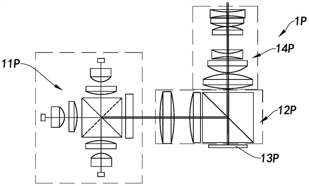
[0004] However, the illuminating beam emitted by the illuminating system 11P of the existing micro-projection system 1P must pass through the bulky and heavy relay lens group 12P to reach the required irradiation area of ​​the LCOS display chip 13P, and transmit the illuminating beam in a diverted manner. , in order to modulate the image light through the LCOS display chip 13P, etc., so that the existing near-eye display system has many shortcomings, such as large size, high cost, heavy equipment, etc., which greatly limits the existing near-eye display system. Consumer development and adoption
In addition, in order to achieve color display, the lighting system 11P has to be equipped with light sources, color combining and light uniforming devices, which further increases the size and volume of the entire near-eye display system, makes the design more complicated, and costs more

Method used


Image

  • Near-eye display device and manufacturing method thereof
  • Near-eye display device and manufacturing method thereof
  • Near-eye display device and manufacturing method thereof

Examples


Embodiment Construction

[0042]The following description serves to disclose the present invention to enable those skilled in the art to carry out the present invention. The preferred embodiments described below are only examples, and those skilled in the art can devise other obvious variations. The basic principles of the present invention defined in the following description can be applied to other embodiments, variations, improvements, equivalents and other technical solutions without departing from the spirit and scope of the present invention.

[0043] Those skilled in the art should understand that in the disclosure of the present invention, the terms "vertical", "transverse", "upper", "lower", "front", "rear", "left", "right", " The orientation or positional relationship indicated by "vertical", "horizontal", "top", "bottom", "inner", "outer", etc. is based on the orientation or positional relationship shown in the drawings, which are only for the convenience of describing the present invention ...


PUM


Abstract

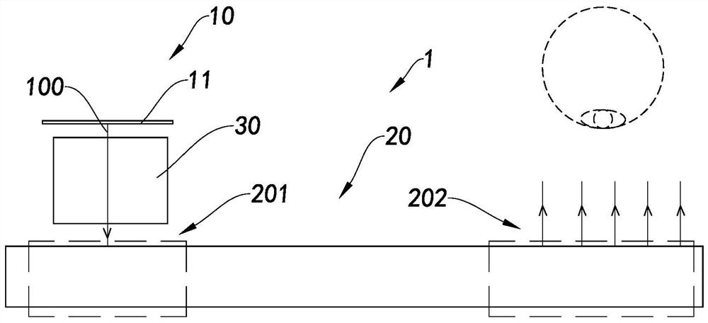
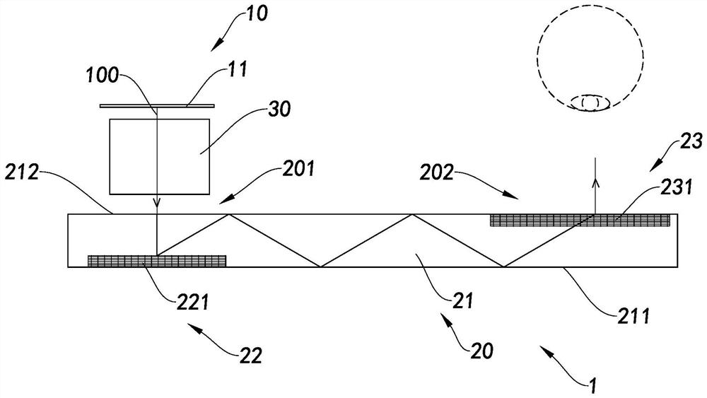
The invention provides a near-eye display device and a manufacturing method thereof. The near-eye display device comprises at least one image source, at least one near-eye display device and at least one imaging lens. The image source comprises a self-luminous display chip for emitting image light. The near-eye display device is provided with at least one coupling-in area and at least one coupling-out area, the coupling-in area of the near-eye display device is correspondingly coupled to the image source, and the near-eye display device is used for coupling the image light in from the coupling-in area and then coupling the image light out from the coupling-out area. Therefore, the near-eye display device does not need to be equipped with an illumination system and a relay system, and a user can watch an image corresponding to the image light through the near-eye display device. And the imaging lens is correspondingly arranged in a light path between the image source and the near-eye display device, and is used for carrying out imaging processing on the image light from the image source and then transmitting the image light to the coupling-in area of the near-eye display device.

Description

technical field [0001] The present invention relates to the technical field of near-eye display, and more particularly to a near-eye display device and a manufacturing method thereof. Background technique [0002] In recent years, the emergence of micro-display chip technology has made miniaturization and high-resolution projection display possible. With the continuous development of LED technology and micro-display chip technology and the large demand of the market, more and more attention has been paid to wearable micro-projection systems with high image quality and small size, especially in today's hot augmented reality (Augmentedreality, AR), near-eye display (Near-eye display, NED) and other fields. [0003] At present, the existing near-eye display system is usually composed of a micro-projection system and a display device, but the micro-projection system has to be configured with a corresponding light source system and a center due to the use of non-self-luminous di...

Claims


Application Information

Patent Timeline
Patent Type & Authority Applications(China)
IPC IPC(8): G02B27/01
CPCG02B27/0101G02B2027/014
Inventor 王雁茹陈杭胡增新
Owner SUNNY OPTICAL ZHEJIANG RES INST CO LTD
Learn More