
Deep foundation pit monitoring system based on Internet of Things

A monitoring system and deep foundation pit technology, applied in the field of construction engineering, can solve the problems that the deep foundation pit cannot support the stress, the protection structure of the deep foundation pit cannot function normally, and cannot be adjusted.

Inactive Publication Date: 2021-06-11
深圳市安比智慧科技有限公司
View PDF10 Cites 0 Cited by
  • Summary
  • Abstract
  • Description
  • Claims
  • Application Information

AI Technical Summary

Problems solved by technology

After the steel support system is erected and locked, the axial force, preload, and prestress are basically the same as the preset, and there is basically no adjustment in the follow-up. This makes it impossible for the steel support system to produce a stable foundation for the deep foundation pit once deformation occurs. Support stress, which in turn causes deformation of the foundation pit enclosure structure, and the protection structure of the deep foundation pit cannot function normally, causing it to have the risk of collapse, which will have a serious impact on the construction personnel, construction equipment and construction progress
If it is necessary to change the supporting stress of the deep foundation pit, it is necessary to make corresponding adjustments according to the collected monitoring data of the deep foundation pit. Due to the fault tolerance and accuracy of the adjustment process of the steel support body, this work is still done by people, and it is impossible to replace the manual and automatic adjustment of the steel support system to change the support stress on the deep foundation pit through the monitoring data of the deep foundation pit.

Method used


Image

  • Deep foundation pit monitoring system based on Internet of Things
  • Deep foundation pit monitoring system based on Internet of Things
  • Deep foundation pit monitoring system based on Internet of Things

Examples


Embodiment Construction

[0067] In order to make the object, technical solution and advantages of the present invention clearer, the present invention will be described in further detail below in conjunction with specific embodiments and with reference to the accompanying drawings.

[0068] It should be noted that, unless otherwise defined, the technical terms or scientific terms used in the embodiments of the present invention shall have the usual meanings understood by those skilled in the art to which the present disclosure belongs. "First", "second" and similar words used in the present disclosure do not indicate any order, quantity or importance, but are only used to distinguish different components. "Comprising" or "comprising" and similar words mean that the elements or items appearing before the word include the elements or items listed after the word and their equivalents, without excluding other elements or items. Words such as "connected" or "connected" are not limited to physical or mechan...


PUM


Abstract

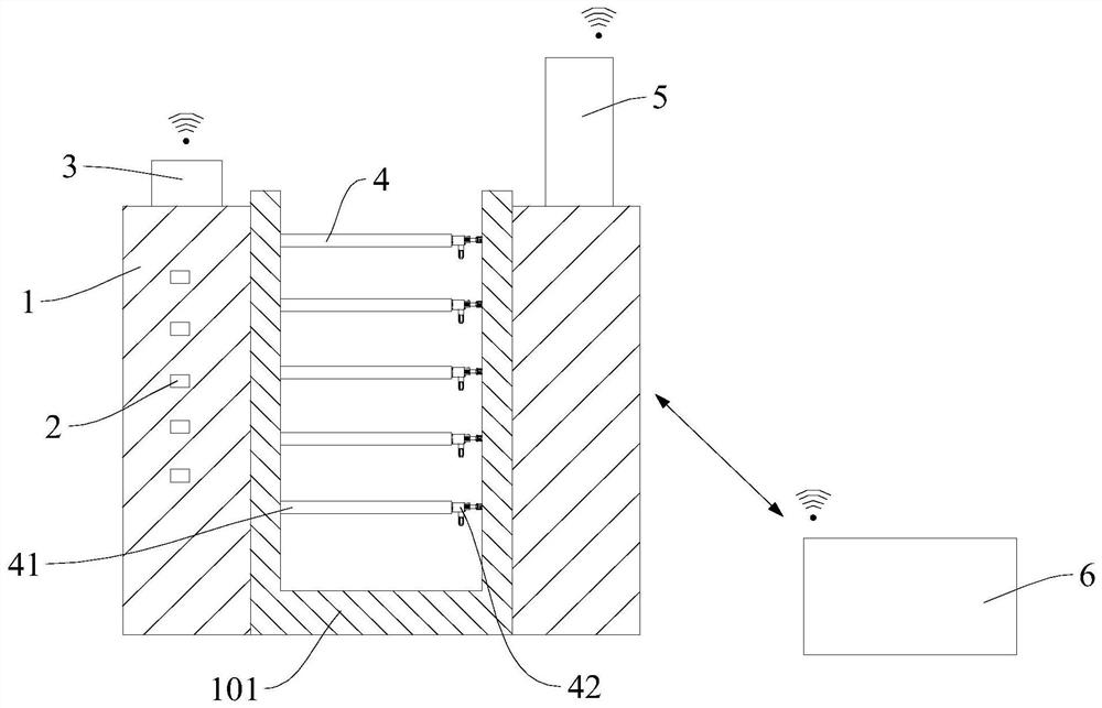
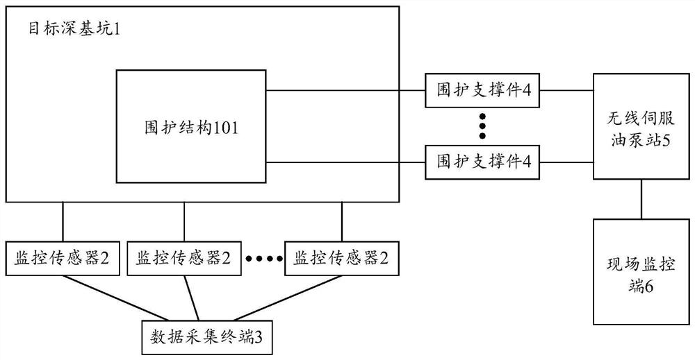
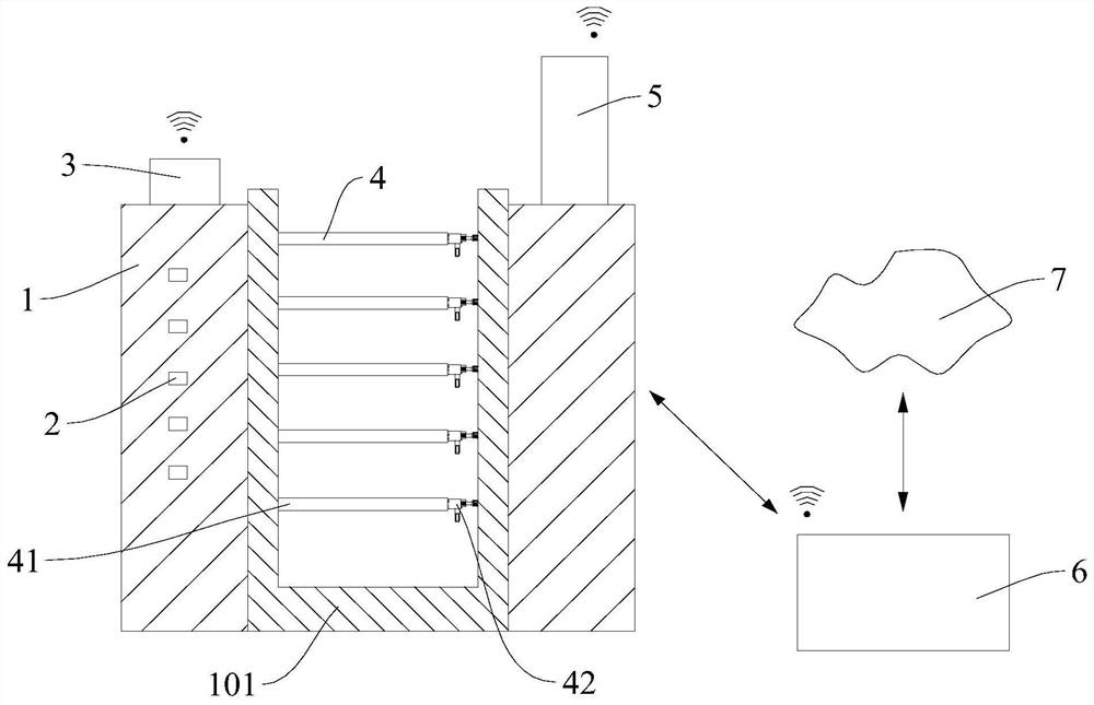
The invention provides a deep foundation pit monitoring system based on the Internet of Things and relates to the technical field of constructional engineering. The system comprises at least one monitoring sensor, a data acquisition terminal, at least one enclosure supporting piece, a wireless servo oil pump station and a field monitoring terminal, wherein the at least one monitoring sensor is installed on a target deep foundation pit internally provided with an enclosure structure, and is used for obtaining monitoring data of the deformation condition of a target deep foundation pit body and the periphery; the data acquisition terminal is wirelessly connected with all the monitoring sensors and is used for summarizing the monitoring data acquired by the monitoring sensors; the enclosure supporting pieces are installed in the enclosure structure and used for stably supporting the enclosure structure; the wireless servo oil pump station is connected with all the enclosure supporting pieces and used for controlling the enclosure supporting pieces to act so as to support the enclosure structure, and collapse of the target deep foundation pit is avoided; the field monitoring terminal is in wireless connection with the data acquisition terminal and the wireless servo oil pump station. According to the remote monitoring system for the deep foundation pit, the monitoring sensor is installed on the target deep foundation pit, 24-hour real-time monitoring is achieved, and comprehensive multiple safety guarantee is provided for the target deep foundation pit and the periphery.

Description

technical field [0001] The invention relates to the technical field of construction engineering, in particular to a deep foundation pit monitoring system based on the Internet of Things. Background technique [0002] Foundation pit engineering mainly includes the design and construction of foundation pit support system and earthwork excavation, which is a highly comprehensive system engineering. It requires close collaboration between geotechnical and structural engineering technicians. The foundation pit support system is a temporary structure and is no longer needed after the completion of the underground construction. The general definition of deep foundation pit is: the bottom area is within 27 square meters, and the long side of the bottom is less than three times the short side, the excavation depth is more than 5 meters (including 5 meters), or the basement is more than three floors (including three floors), or the depth is not Projects that do not exceed 5 meters, ...

Claims


Application Information

Patent Timeline
IPC IPC(8): G05B19/042
CPCG05B19/0428G05B2219/24024
Inventor 鄢必超
Owner 深圳市安比智慧科技有限公司
Learn More