COB module repairing method

A repair method and technology for dead lights, applied in semiconductor devices, electrical components, circuits, etc., can solve problems such as low efficiency, broken modules, complicated and complicated procedures, etc., to reduce the number of repairs and improve the efficiency of dead lights. The effect of repairing

Active Publication Date: 2021-06-11
HCP TECH CO LTD
View PDF14 Cites 3 Cited by
  • Summary
  • Abstract
  • Description
  • Claims
  • Application Information

AI Technical Summary

Problems solved by technology

The process is cumbersome and complicated, the efficiency is low, and there is no mechanized means, and the reflow soldering in the die-bonding process may cause new dead lights, making the module more and more damaged, and repeated repairs

Method used


Image

  • COB module repairing method
  • COB module repairing method
  • COB module repairing method

Examples


Embodiment Construction

[0045] In order to make the purpose, features and advantages of the present invention more obvious and understandable, the technical solutions in the embodiments of the present invention will be clearly and completely described below in conjunction with the accompanying drawings in the embodiments of the present invention. Obviously, the following description The embodiments are only some of the embodiments of the present invention, but not all of them. Based on the embodiments of the present invention, all other embodiments obtained by persons of ordinary skill in the art without making creative efforts belong to the protection scope of the present invention.

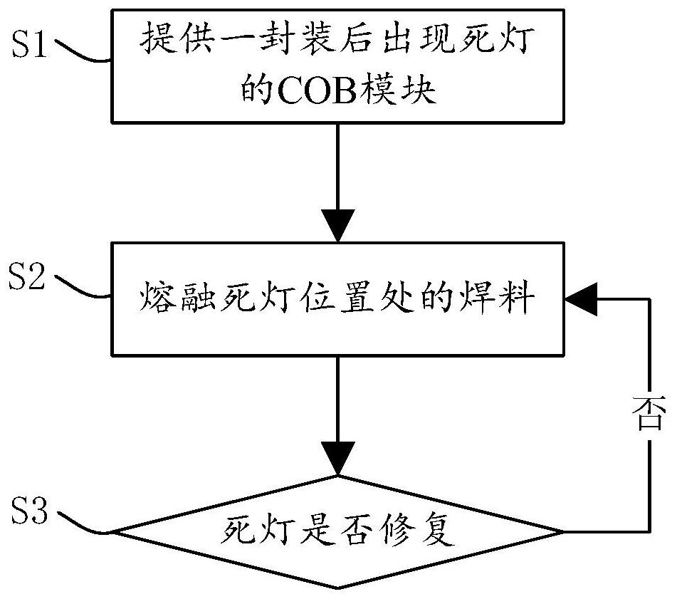
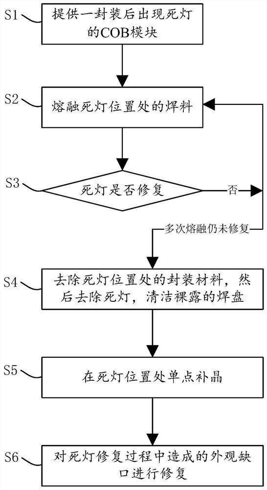
[0046] At present, after the COB module is packaged, dead lights will occur due to insufficient soldering and other reasons. The repair method adopted in the prior art is usually: digging out the cured glue directly, then removing the LED chip and residual solder, and then re-bonding the die and pressing the film.

[...


PUM


Abstract

The invention discloses a COB module repairing method. The method comprises the following steps of providing a COB module with an LED damage after packaging; melting the solder at the LED damage position; and if the LED damage is still not repaired, melting the welding flux at the dead lamp position repeatedly. According to the COB module repairing method provided by the invention, chip-level repairing can be realized through a fixed-point heating mode, the times of glue digging, crystal fixing and film pressing repairing are greatly reduced, and then single-point crystal supplementing repairing is carried out on the remaining LED damage positions which cannot be repaired through the fixed-point heating mode. According to the COB module repairing method, the dead lamp repairing efficiency can be greatly improved.

Description

technical field [0001] The invention belongs to the field of display technology, in particular to a method for repairing a COB module. Background technique [0002] With the continuous development of society and the vigorous advocacy of the country, the LED industry has become one of the most active industries today, and LED display products have gradually entered various fields of society and life. At the same time, with the innovation and development of LED display technology, the small-pitch LED display module with high resolution per unit area has become the mainstream product of LED display, which can display higher-definition graphics, images and videos. It can also display more video and image images, especially in the application of image stitching, which can achieve arbitrary large-area stitching. [0003] Among the current LED display products, Mini-LED COB (chip on board) products are favored because they can provide small-pitch products. In the current producti...

Claims


Application Information

Patent Timeline
Patent Type & Authority Applications(China)
IPC IPC(8): H01L33/62H01L33/48
CPCH01L33/62H01L33/48H01L2933/0066H01L2933/0033
Inventor 卢敬权薛水源钟宇宏庄文荣孙明
Owner HCP TECH CO LTD
Why Eureka
Try Eureka