Tissue distraction device for orbital bone surgery

A technique for orbital surgery, which is applied in the field of auxiliary support devices for orbital bone surgery, can solve the problems of small operating space for orbital bone surgery, unfixed support devices, and low work efficiency, so as to reduce incision support and pull auxiliary personnel and reduce work costs. Good strength and versatility

Active Publication Date: 2021-06-15
THE AFFILIATED HOSPITAL OF QINGDAO UNIV
View PDF13 Cites 0 Cited by
  • Summary
  • Abstract
  • Description
  • Claims
  • Application Information

AI Technical Summary

Problems solved by technology

[0003] The purpose of the present invention is to overcome the shortcomings of the prior art, and propose to design a tissue stretching device for orbital bone surgery, to solve the problem of small and inconvenient operation space for orbital bone surgery, and to overcome the auxiliary function of stretching the incision in the operation. Solve the problems of many personnel, high work intensity and low work efficiency, solve the problem that the soft tissue in the orbit is easy to rush to the surgical field of view and block the line of sight, and overcome the problem that the support device is not fixed and easy to shift

Method used


Image

  • Tissue distraction device for orbital bone surgery
  • Tissue distraction device for orbital bone surgery
  • Tissue distraction device for orbital bone surgery

Examples


Embodiment 1

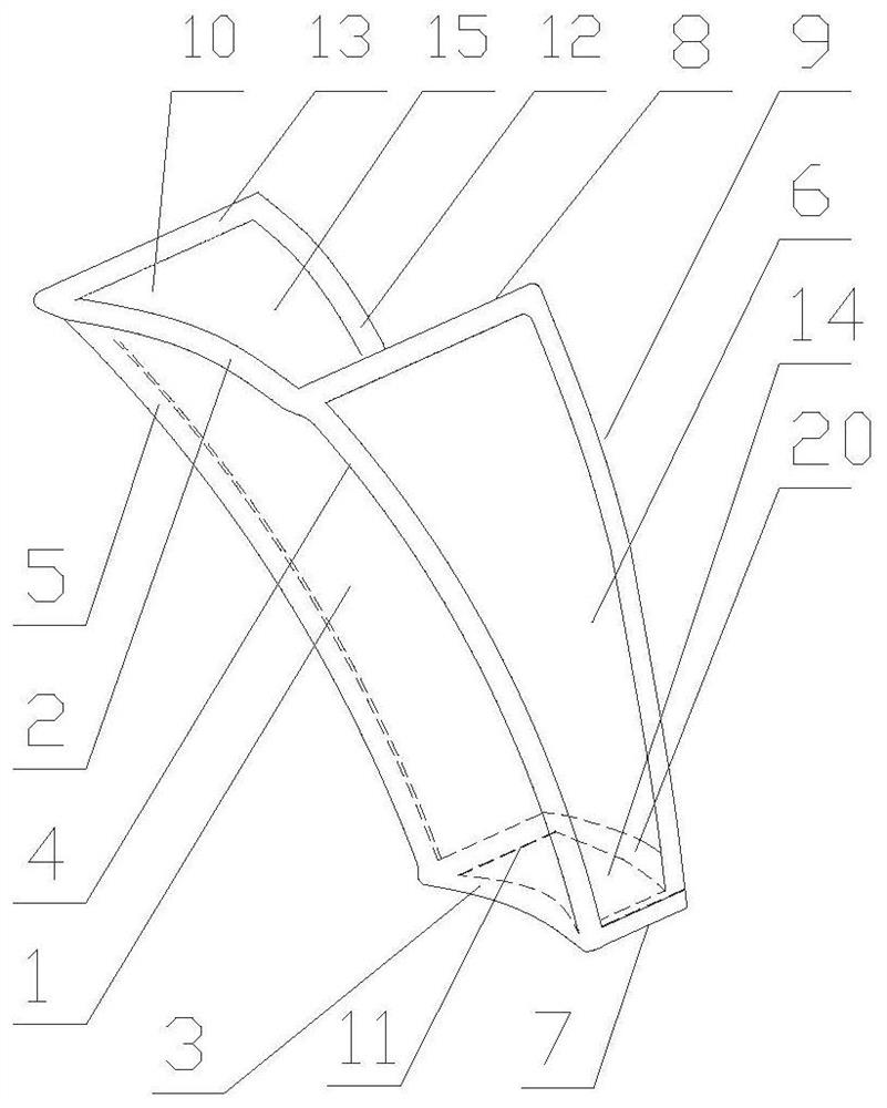
[0019]The tissue spreading device for orbital bone surgery involved in this embodiment has a main structure comprising: an arc-shaped wall 1, a first support frame 2, a second support frame 3, a third support frame 4, a fourth support frame 5, First side wall 6, fifth support frame 7, sixth support frame 8, seventh support frame 9, second side wall 10, eighth support frame 11, ninth support frame 12, tenth support frame 13, bottom wall 14. The eleventh supporting frame 20, the retaining chamber 15; the curved wall 1 is a curved curved surface to adapt to the curvature of the eyeball and protect the eyeball; the upper, lower, left and right edges of the curved wall 1 are respectively It is the first support frame 2, the second support frame 3, the third support frame 4, and the fourth support frame 5. The four support frames are all integrated with the arc-shaped wall 1, and are curved edges. The first support frame 2 The arc length is greater than the arc length of the second ...

Embodiment 2

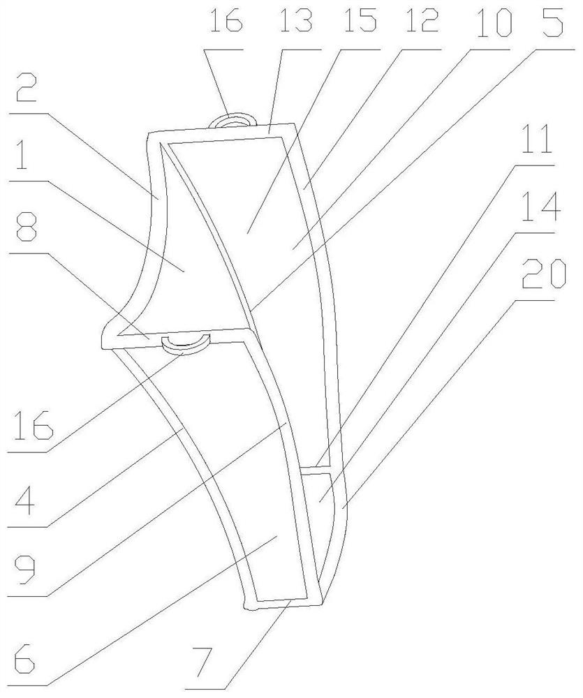
[0023] The supporting device for orbital bone surgery involved in this embodiment has the same main structure as that of Embodiment 1, and the middle position of the sixth support frame 8 and the middle position of the tenth support frame 13 are respectively fixed with a fixed ring 16 with an integral structure , the fixing ring 16 is a semi-circular ring structure. When in use, push the retaining device into the muscular tissue between the orbital bone and the eyeball, and then use surgical sutures to suture the fixing ring 16 temporarily on the surrounding tissue, and the retaining device The device is further secured to prevent deflection of the spacer, and the sutures can be removed at the end of the procedure.

Embodiment 3

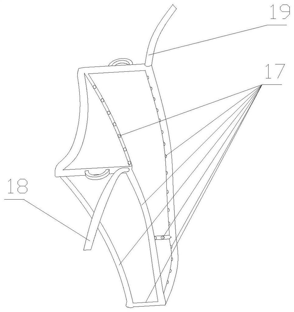
[0025] The supporting device for orbital bone surgery involved in this embodiment, its main structure is the same as that of embodiment 1 or embodiment 2, each of the support frames described is a tube structure, and the pipelines of each support frame are connected; the second support frame 3 , the third support frame 4, the fourth support frame 5, the fifth support frame 7, the seventh support frame 9, the eighth support frame 11, the ninth support frame 12, the pipeline of the eleventh support frame 20 are evenly provided with supports The small hole 17 of the tube, the small hole 17 of the support tube is located on the side of the inner surface of each support frame pipe close to the support cavity 15, which is convenient for suctioning the liquid infiltrated in the support cavity 15, and avoids the small hole 17 of the support tube from facing the side of the muscle tissue , causing the small hole 17 of the support tube to be blocked by the surrounding soft tissue during ...


PUM


Abstract

The invention belongs to the technical field of medical auxiliary instruments, and relates to a tissue distraction device for an orbital bone surgery. A main body structure comprises an arc-shaped wall, a first supporting frame, a second supporting frame, a third supporting frame, a fourth supporting frame, a first side wall, a fifth supporting frame, a sixth supporting frame, a seventh supporting frame, a second side wall, an eighth supporting frame, a ninth supporting frame, a tenth supporting frame, a bottom wall, an eleventh supporting frame and a supporting and blocking cavity, the arc-shaped wall is a bent cambered surface so as to adapt to the radian of an eyeball and protect the eyeball, the seventh supporting frame on the outer side edge of the first side wall is of an arc-shaped structure, the area formed by the arc-shaped wall, the first side wall, the second side wall and the bottom wall is the supporting and blocking cavity, and the supporting and blocking space area is used for orbital bone surgery operation. The incision supporting and pulling assisting personnel are reduced, the working intensity is reduced, the operation efficiency is improved, surrounding tissues are effectively protected, infiltrated blood is effectively prevented from blocking sight lines, the overall structural design is simple and ingenious, operation and popularization are convenient, and the application environment is friendly.

Description

Technical field: [0001] The invention belongs to the technical field of medical auxiliary equipment, and relates to an auxiliary supporting device for orbital bone surgery, in particular to a device fixed between the orbital bone and the eyeball to open up an operating space for the operation, so as to reduce the number of auxiliary operators , Release the operation space and improve the operation efficiency. Background technique: [0002] The orbit is located in the middle of the craniofacial and protrudes slightly forward. It is a four-sided conical bone socket. Its opening is forward, the cone is backward and slightly medial. The adult orbital depth is 40-50mm, and the other three bone walls except the lateral wall are relatively thin. When subjected to external force, the continuity of the orbital bone and the fracture of the cortical bone are prone to occur, that is, orbital fractures. After the orbital fracture occurs, in mild cases, the intraorbital muscles will be i...

Claims


Application Information

Patent Timeline
Patent Type & Authority Applications(China)
IPC IPC(8): A61F9/007A61B90/17
CPCA61F9/007A61B90/17
Inventor 梁涛张凌云孙学国
Owner THE AFFILIATED HOSPITAL OF QINGDAO UNIV
Why Eureka
Try Eureka