Pipe expanding device

A technology of tube expansion device and expansion head, applied in geothermal energy power generation, heat exchange equipment and other directions, can solve the problems of poor expansion tube, affecting the service life of expansion rod, and distortion of expansion rod, so as to reduce the probability of distortion and prolong the service life. Effect

Active Publication Date: 2021-06-15
ZHONGSHAN POLYTECHNIC
View PDF9 Cites 0 Cited by
  • Summary
  • Abstract
  • Description
  • Claims
  • Application Information

AI Technical Summary

Problems solved by technology

[0003] For some larger heat exchangers, correspondingly, the length of the expansion rod is longer, so the requirement for the anti-deformation ability of the expansion rod is also higher. The traditional expansion method is realized by using the expansion rod to jack up. After long-term production, it will inevitably cause the problem of twisting of the expansion rod, which not only affects the service life of the expansion rod, but also easily causes poor expansion

Method used


Image

  • Pipe expanding device
  • Pipe expanding device

Examples


Embodiment Construction

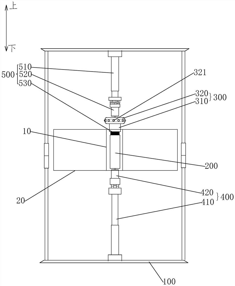
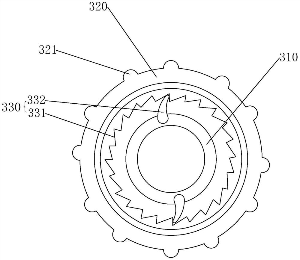
[0020] Embodiments of the present invention are described in detail below, examples of which are shown in the drawings, wherein the same or similar reference numerals designate the same or similar elements or elements having the same or similar functions throughout. The embodiments described below by referring to the figures are exemplary only for explaining the present invention and should not be construed as limiting the present invention.

[0021] In the description of the present invention, it should be understood that when referring to orientation descriptions, such as terms "upper", "lower", "front", "rear", "left", "right", "vertical", "horizontal" ", "top", "bottom", "inner", "outer" and other indicated orientations or positional relationships are based on the orientations or positional relationships shown in the drawings, and are only for the convenience of describing the present invention and simplifying the description, rather than indicating Or imply that the devic...


PUM


Abstract

The invention discloses a pipe expanding device. The pipe expanding device comprises a rack, a pull rod, an expanding head and a driving mechanism. A positioning mechanism is arranged on the rack, and the positioning mechanism is used for positioning a heat exchanger, wherein a pipe fitting is fixedly arranged on the heat exchanger in a penetrating manner. The pull rod is movably arranged on the rack, is arranged in the pipe fitting in a penetrating manner and extends in the axial direction of the pipe fitting. The expanding head is detachably connected to the top of the pull rod and is matched with the inner diameter of the pipe fitting. The driving mechanism is connected with the pull rod and is used for driving the expanding head to move up and down and rotate. According to the pipe expanding device of the above structure, an expanded rod is composed of the pull rod and the expanding head, the expanding head is detachably connected to the pull rod, before pipe expanding operation, the pull rod upwards penetrates through the to-be-expanded pipe fitting, then the expanding head is installed at the top of the pull rod, the driving mechanism drives the pull rod to move downwards and rotate so that the expanding head can rotate in the process of moving downwards relative to the inner wall of the pipe fitting, the expanding head is prevented from directly and rigidly colliding with the inner wall of the pipe fitting, the distortion probability of the expanded rod is reduced, and the service life of the expanded rod is prolonged.

Description

technical field [0001] The invention relates to the technical field of heat exchangers, in particular to a tube expansion device. Background technique [0002] In the prior art, most heat exchangers use a structure combining heat dissipation fins and heat exchange tubes. When manufacturing heat exchangers, the general practice is to stamp the heat dissipation fins in advance to form perforations for the heat exchange tubes to pass through. , and then the heat exchange tube is pierced on the perforation, and then the expansion rod whose head size is larger than the inner diameter of the heat exchange tube is pushed into the heat exchange tube to realize tube expansion, thereby fixing the heat exchange tube on the heat dissipation fin. [0003] For some larger heat exchangers, correspondingly, the length of the expansion rod is longer, so the requirements for the anti-deformation ability of the expansion rod are also higher. The traditional expansion method is realized by usin...

Claims


Application Information

Patent Timeline
Patent Type & Authority Applications(China)
IPC IPC(8): B21D39/06B21D53/02
CPCB21D39/06B21D53/02Y02E10/10
Inventor 富阳
Owner ZHONGSHAN POLYTECHNIC
Why Eureka
Try Eureka