Forming device capable of realizing automatic demolding and used for prefabricated part

An automatic demoulding and forming device technology, applied in the direction of unloading devices, manufacturing tools, etc., can solve the problems of low demoulding efficiency, damage to prefabricated parts, high experience requirements, etc., achieve high demoulding quality, stable molding, and prevent bending The effect of the mold

Inactive Publication Date: 2021-06-15
祝锡明
View PDF5 Cites 1 Cited by
  • Summary
  • Abstract
  • Description
  • Claims
  • Application Information

AI Technical Summary

Problems solved by technology

[0005] Aiming at the deficiencies of the prior art, the present invention provides a molding device for prefabricated parts capable of automatic demoulding, which has the advantages of automatic demoulding, high demoulding quality, fast efficiency, prevention of mold bending, and stable molding. Compared with the existing concrete prefabricated parts forming device, it is necessary to manually knock the mold during demoulding, so that the prefabricated part is separated from the mold. Manual knocking requires high experience, and it is difficult to ensure a suitable knocking force, which is easy to cause damage to the prefabricated part. And the manual demoulding time is long and the demoulding efficiency is low

Method used


Image

  • Forming device capable of realizing automatic demolding and used for prefabricated part
  • Forming device capable of realizing automatic demolding and used for prefabricated part
  • Forming device capable of realizing automatic demolding and used for prefabricated part

Examples


Embodiment Construction

[0024] The following will clearly and completely describe the technical solutions in the embodiments of the present invention with reference to the accompanying drawings in the embodiments of the present invention. Obviously, the described embodiments are only some, not all, embodiments of the present invention. Based on the embodiments of the present invention, all other embodiments obtained by persons of ordinary skill in the art without making creative efforts belong to the protection scope of the present invention.

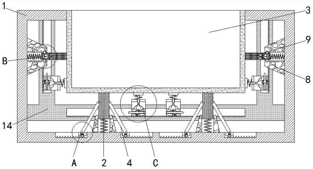
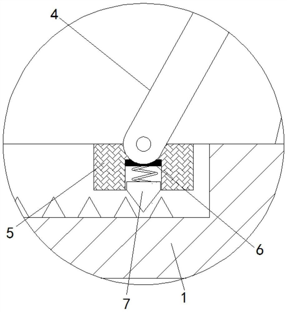
[0025] see Figure 1-4 , a molding device for prefabricated parts capable of automatic demoulding, comprising a casing 1, a chute is provided at the inner bottom of the casing 1, and a slider 5 is slidably connected inside the chute, and a ratchet groove is provided on the inner wall of the chute, The ratchet groove is used in conjunction with the ratchet block 7 to limit the sliding of the slider 5. The inner bottom of the shell 1 is slidably connected to the...


PUM


Abstract

The invention relates to the technical field of concrete prefabricated parts, and discloses a forming device capable of realizing automatic demolding and used for a prefabricated part. The forming device comprises a shell, a support rod is glidingly connected to the inner bottom of the shell, a mold is fixedly connected to the top of the support rod, a supporting rod is movably connected to the outer side of the support rod, a sliding box is glidingly connected to the interior of a guide rail, a gear is fixedly connected to the interior of the sliding box, a cam is fixedly connected to the front surface of the gear, an ejector rod is glidingly connected to the interior of the sliding box, a rubber hammer is glidingly connected to the top of the sliding box, and the outer side of the rubber hammer is sleeved with a supporting spring. According to the forming device capable of realizing automatic demolding and used for the prefabricated part, the gear rotates to drive the sliding box to move under the action of a tooth groove, the sliding box drives the rubber hammer to move, meanwhile, the gear rotates to drive the cam to rotate, the cam drives the rubber hammer to slide, and then through cooperative use of the rubber hammer and the supporting spring, the effects of automatic demolding and high demolding quality are achieved.

Description

technical field [0001] The invention relates to the technical field of concrete prefabricated parts, in particular to a forming device for prefabricated parts capable of automatic demoulding. Background technique [0002] Concrete prefabricated parts are called PC components in the field of residential industrialization, such as prefabricated reinforced concrete column foundations, prefabricated steel structure steel column foundations, street lamp billboard column reinforced concrete foundations, and prefabricated floors. The corresponding traditional cast-in-place concrete requires a construction site On-site formwork, on-site pouring and on-site maintenance, concrete precast parts are widely used in construction, transportation, water conservancy and other fields, and play an important role in the national economy. [0003] The existing concrete prefabricated parts forming device needs to manually knock the mold during demoulding to separate the prefabricated part from th...

Claims


Application Information

Patent Timeline
Patent Type & Authority Applications(China)
IPC IPC(8): B28B13/06
CPCB28B13/067
Inventor 祝锡明
Owner 祝锡明
Why Eureka
Try Eureka