Flexible cooling equipment for light diffusion plate
A technology of cooling equipment and light diffusion plate, applied in the field of mechanical equipment, can solve the problems of light diffusion plate temperature drop, internal structure damage, product quality decline, etc., and achieve the effects of improving product quality, convenient protection, and avoiding damage
- Summary
- Abstract
- Description
- Claims
- Application Information
AI Technical Summary
Problems solved by technology
Method used
Image

Examples
Embodiment Construction
[0021] The specific implementation manners of the present invention will be further described in detail below in conjunction with the accompanying drawings and embodiments. The following examples are used to illustrate the present invention, but are not intended to limit the scope of the present invention.
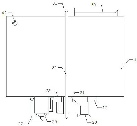
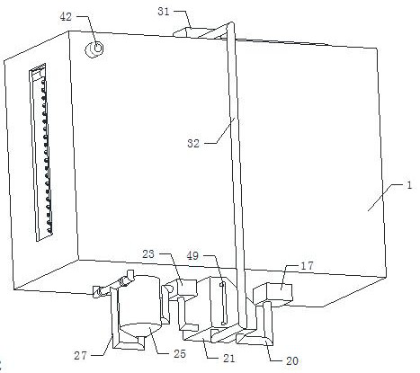
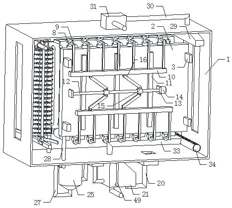
[0022] Such as Figure 1 to Figure 7 As shown, a light diffusion plate flexible cooling device of the present invention, when it is working, the light diffusion plate extruded at high temperature from the outside extends into the working chamber 1 through the material opening on the right side of the working chamber 1, and the air cooling mechanism diffuses the light The plate is blown to cool down, so that its temperature is initially lowered. The light diffusion plate that has been air-cooled moves to the left between the two groups of water-cooling mechanisms, and the refrigeration mechanism is opened. The refrigeration mechanism discharges the cooled water into the two...
PUM
 Abstract
Description
Claims
Application Information
PatSnap Eureka turns technology decisions into work you can execute. Powered by our Innovation Knowledge Graph, it runs expert workflows across engineering, life sciences, materials and intellectual property. Get your review-ready output in minutes.


