Traction machine with long service life

A traction machine and life-span technology, which is applied in the field of traction machines, can solve the problems of increasing the overall length of the rotor shaft, increasing the processing cost and difficulty of the rotor shaft, and increasing the cost of equipment, so as to improve the working stability and service life, reduce the The overall shape and equipment cost, and the effect of avoiding uneven force

Pending Publication Date: 2021-06-15
ZHEJIANG MATO DRIVE EQUIP +1
View PDF7 Cites 0 Cited by
  • Summary
  • Abstract
  • Description
  • Claims
  • Application Information

AI Technical Summary

Problems solved by technology

However, because the traction sheave of this kind of traction machine is installed at the end of the rotor shaft, the rotor shaft will be subjected to radial pressure from the end during operation, which will cause the problem of uneven force on the rotor shaft, which will seriously increase The pressure caused by the rotor shaft on the side close to the traction sheave to the frame
This connection position not only requires a large-scale force-bearing bearing to improve the connection stability, resulting in an increase in equipment costs; but also needs to adjust the size of the machine base at this connection position and set up a variety of reinforcement structures, resulting in the overall failure of the traction machine. Increased size and increased design difficulty
[0003] On the other hand, since the rotor shaft needs to extend to the outside of the frame and connect to the traction sheave, the overall length of the rotor shaft will increase, which will not only further increase the force on the frame at the connection position, but also increase the processing cost and difficulty of the rotor shaft. It will also increase accordingly, further increasing the cost of equipment
[0004] In addition, the existing rotor yoke and traction sheave are all split structures, which need to be connected through the structure of bolts and pins, or indirectly connected through the rotor shaft to transmit torque; The position accuracy of the holes is required to be high, and there is a risk of crushing bolts, pins or connecting keys, which reduces the working stability and service life of the traction machine
[0005] Therefore, the existing traction machine has the problems of high equipment cost, low working stability and short service life

Method used


Image

  • Traction machine with long service life

Examples


Embodiment Construction

[0021] The present invention will be further described below in conjunction with the accompanying drawings and embodiments, but not as a basis for limiting the present invention.

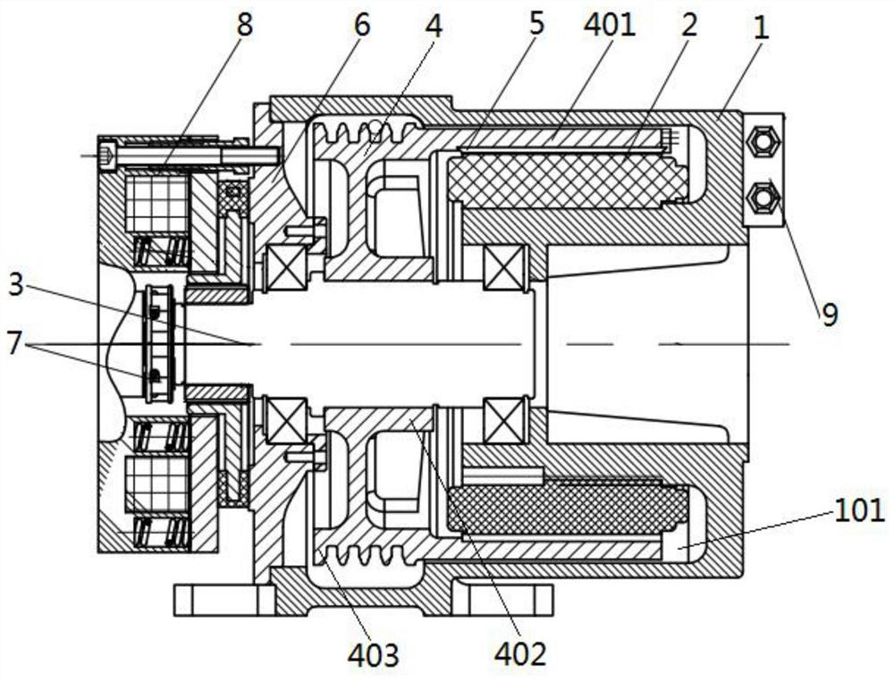
[0022] Example. Traction machine with long service life, constituted as figure 1 As shown, it includes a machine base 1, a stator core 2, a rotor shaft 3 and a traction wheel 4, wherein the stator core 2 is a stator core with windings, and the two sides of the rotor shaft 3 are connected to the machine base 1 through bearing rotation, The middle part of the rotor shaft 3 is connected to the traction sheave 4 , and the outer upper end of the traction sheave 4 extends into the base 1 and is provided with a rotor yoke 401 , which is integrally formed with the traction sheave 4 .

[0023] One side of the base 1 is provided with an annular iron core chamber 101. The cross-sectional shape of the iron core chamber 101 is U-shaped. The stator core 2 is sleeved on the inner ring of the iron core chamber 101...


PUM


Abstract

The invention discloses a traction machine with long service life, which comprises a machine base (1), a stator iron core (2), a rotor shaft (3) and a traction wheel (4), the two sides of the rotor shaft (3) are rotationally connected with the machine base (1), the middle of the rotor shaft (3) is connected with the traction wheel (4), a rotor magnet yoke (401) is arranged outside the traction wheel (4), and the rotor magnet yoke (401) and the traction wheel (4) are integrally formed. The traction wheel is arranged in the middle of the rotor shaft, so that the connecting positions of the two ends of the rotor shaft are uniformly stressed, the working stability of the traction wheel is improved, and the required length of the rotor shaft is shortened; and the rotor magnet yoke and the traction wheel are integrally formed, and a connecting piece structure in an original traction machine can be omitted, so that the machining difficulty of equipment is reduced, and the torque transmission stability of the traction machine is improved.

Description

technical field [0001] The invention relates to a traction machine, in particular to a traction machine with long service life. Background technique [0002] The current traction machine is mainly composed of a frame, a stator, a rotor and a traction wheel. The stator core is fixed in the cavity of the frame, and the rotor yoke and magnetic steel sleeve are set outside the stator and connected to the rotor shaft located in the middle of the frame. At the same time, the middle part of the rotor shaft is positioned by connecting the machine base with bearings, and one end of the rotor shaft extends to the outside of the machine base and connects with the traction wheel. During operation, the rotor drives the rotor shaft and the traction wheel to rotate in turn. However, because the traction sheave of this kind of traction machine is installed at the end of the rotor shaft, the rotor shaft will be subjected to radial pressure from the end during operation, which will cause the ...

Claims


Application Information

Patent Timeline
Patent Type & Authority Applications(China)
IPC IPC(8): B66B11/04B66B11/00
CPCB66B11/043B66B11/0035
Inventor 邵佳伟钱士亮钦小铭吴骏
Owner ZHEJIANG MATO DRIVE EQUIP
Why Eureka
Try Eureka