Switching valve and water outlet device

A technology for switching valves and waterways, applied in the direction of valve devices, valve operation/release devices, sliding valves, etc., to achieve the effect of blocking and solving the sealing effect

Pending Publication Date: 2021-06-15
FUJIAN XIHE SANITARY WARE TECH
View PDF0 Cites 0 Cited by
  • Summary
  • Abstract
  • Description
  • Claims
  • Application Information

AI Technical Summary

Problems solved by technology

[0003] The purpose of the present invention is to overcome the above-mentioned defects or problems in the background technology, and provide a switching valve and a water outlet device. Each waterway is set independently, and the water flow in the two waterways will not cause mixing or pollution problems

Method used


Image

  • Switching valve and water outlet device
  • Switching valve and water outlet device
  • Switching valve and water outlet device

Examples


Embodiment Construction

[0036] The following will clearly and completely describe the technical solutions in the embodiments of the present invention with reference to the drawings in the embodiments of the present invention. Obviously, the described embodiments are preferred embodiments of the invention and should not be seen as excluding other embodiments. Based on the embodiments of the present invention, all other embodiments obtained by persons of ordinary skill in the art without creative efforts fall within the protection scope of the present invention.

[0037] In the claims, description and above-mentioned drawings of the present invention, unless otherwise clearly defined, the terms "first", "second" or "third" are used to distinguish different objects, not for Describe a specific order.

[0038] In the claims, specification and above-mentioned drawings of the present invention, unless otherwise clearly defined, for orientation words, such as using the terms "center", "transverse", "longit...


PUM


Abstract

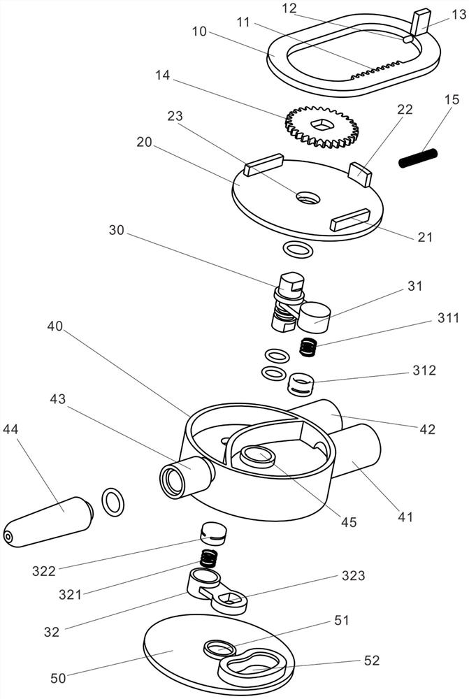
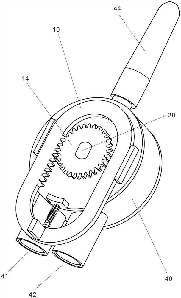
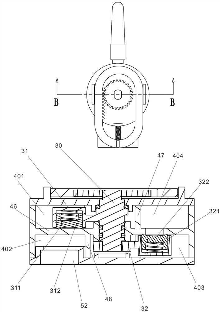
The invention discloses a switching valve and a water outlet device. The switching valve comprises a body and a plugging part; the body is provided with a first water passing path and a second water passing path which are mutually independent; the first water passing path and the second water passing path are provided with a first water passing port and a second water passing port for controlling the on-off of respective water paths; the plugging part is rotationally connected to the body; a first plugging block and a second plugging block are arranged on the plugging part in the axial direction in a staggered mode; the first plugging block and the second plugging block rotate relative to the body to plug or be far away from the first water passing port and the second water passing port; and when one plugging block plugs the corresponding water passing port, the other plugging block is far away from the corresponding water passing port. The water outlet device is provided with the switching valve, so that the two water paths can be controlled at the same time through one control unit, the two water paths are independently arranged, and water flows in the two water paths cannot be mixed or polluted.

Description

technical field [0001] The invention relates to the technical field of valves, in particular to a switching valve and a water outlet device. Background technique [0002] The existing switching valve generally enters the valve body through a water channel, and then flows out of different water channels through the water distribution mechanism. The existing switching valve structure requires a shared water channel, such as a common water inlet chamber or a common process. The water cavity, which makes it possible for some application scenarios with special requirements, such as the output of sterile water, raw water, pure water and other water flows of different water quality, to have the problem of pollution if there is a shared waterway, and if all the waterways are separated , you need to individually control the on-off of each waterway, which in turn leads to the inconvenience of the overall control. Contents of the invention [0003] The purpose of the present inventi...

Claims


Application Information

Patent Timeline
IPC IPC(8): F16K11/074F16K27/04F16K3/314F16K31/54
CPCF16K11/0746F16K27/045F16K3/314F16K31/54F16K31/535
Inventor 林孝发林孝山郑永智邓飞明陈志伟邓小清刘启乔
Owner FUJIAN XIHE SANITARY WARE TECH
Why Eureka
Try Eureka