
Ultrasonic wind sensor with heating function
A wind sensor and ultrasonic technology, applied in the field of ultrasonic wind sensors, can solve problems affecting the detection results of ultrasonic wind sensors, freezing of water in ultrasonic wind sensors, affecting the normal operation of ultrasonic wind sensors, etc.
- Summary
- Abstract
- Description
- Claims
- Application Information
AI Technical Summary
Problems solved by technology
Method used
Image

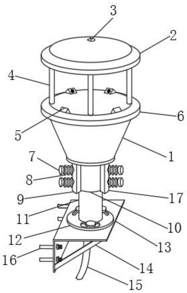
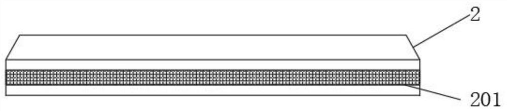
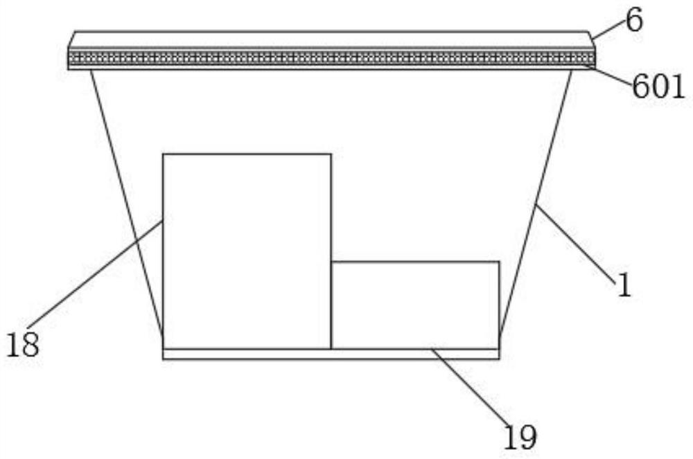
Examples
example 1
[0045] Step S1: Obtain the horizontal wind direction, mark the horizontal wind direction angle as a, and the range of a is (0°, 360°);
[0046] Step S2: When the horizontal wind direction a is 0°, the positive end of the communication cable 15 outputs a 50% duty cycle signal, and the negative end of the communication cable 15 outputs a high-level signal;
[0047] Step S3: Obtain the real-time output current of the communication cable 15, and mark the real-time output current of the communication cable 15 as I OUT ; The lower limit of the current output range of the communication cable 15 is marked as I MIN , mark the upper limit of the current output range of the communication cable 15 as I MAX , mark the upper limit of the range of wind speed detection as P MAX , mark the lower limit of the range of wind speed detection as P MIN ;
[0048] Step S4: By formula P OUT =α×(I OUT -I MIN )×(P MAX -P MIN ) / (I MAX -I MIN ) to obtain the actual wind speed monitoring value P...
example 2
[0051] Step S1: Obtain the horizontal wind direction, mark the horizontal wind direction angle as a, and the range of a is (0°, 360°);
[0052] Step S2: When the horizontal wind direction a is 90°, the positive end of the communication cable 15 outputs a high-level signal, and the negative end of the communication cable 15 outputs a 50% duty cycle signal;
[0053] Step S3: Obtain the real-time output current of the communication cable 15, and mark the real-time output current of the communication cable 15 as I OUT ; The lower limit of the current output range of the communication cable 15 is marked as I MIN , mark the upper limit of the current output range of the communication cable 15 as I MAX , mark the upper limit of the range of wind speed detection as P MAX , mark the lower limit of the range of wind speed detection as P MIN ;
[0054] Step S4: By formula P OUT =α×(I OUT -I MIN )×(P MAX -P MIN ) / (I MAX -I MIN ) to obtain the actual wind speed monitoring value ...
example 3
[0057] Step S1: Obtain the horizontal wind direction, mark the horizontal wind direction angle as a, and the range of a is (0°, 360°);
[0058] Step S2: When the horizontal wind direction a is 180°, the positive end of the communication cable 15 outputs a 50% duty cycle signal, and the negative end of the communication cable 15 outputs a low-level signal;
[0059] Step S3: Obtain the real-time output current of the communication cable 15, and mark the real-time output current of the communication cable 15 as I OUT ; The lower limit of the current output range of the communication cable 15 is marked as I MIN , mark the upper limit of the current output range of the communication cable 15 as I MAX , mark the upper limit of the range of wind speed detection as P MAX , mark the lower limit of the range of wind speed detection as P MIN ;
[0060] Step S4: By formula P OUT =α×(I OUT -I MIN )×(P MAX -P MIN ) / (I MAX -IMIN ) to obtain the actual wind speed monitoring value P ...
PUM
 Abstract
Description
Claims
Application Information