
A method for realizing unidirectionally enhanced photonic spin Hall effect shift

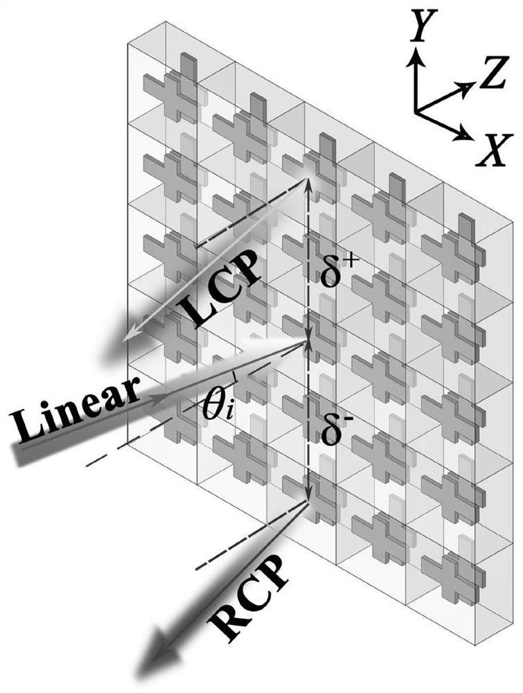
A technology of spin Hall effect and unidirectional enhancement, which is applied in the field of optical microstructure, can solve the problems that the negative influence has not been overcome, limit the enhancement effect, etc., and achieve the effect of small size, high angle sensitivity, and enhanced lateral displacement

Active Publication Date: 2021-12-21
NANJING UNIV OF AERONAUTICS & ASTRONAUTICS
View PDF0 Cites 0 Cited by
  • Summary
  • Abstract
  • Description
  • Claims
  • Application Information

AI Technical Summary

Problems solved by technology

However, considering the higher-order terms, the denominator of the initial displacement formula must be added to the denominator of the partial derivative term and the square of the tangent term. The existence of these two items will reduce the lateral offset
[0005] Although in recent years, researchers have proposed some methods to further enhance the subwavelength scale displacement, such as graphene, hyperbolic metamaterials, surface plasmon resonance, near-zero dielectric constant materials and time-reversal symmetric metamaterials, etc. etc., but in these theoretical or experimental structures, researchers often pay too much attention to changing different materials to achieve a larger reflectance ratio of p-polarization and s-polarization, so that the higher-order terms on the denominator still exist, Its negative effects have not been overcome, which limits the enhancement effect of lateral displacement (in theory, it can reach half of the incident beam waist radius ω 0 / 2)
At the same time, most of these studies are applicable to a single incident linearly polarized beam. Therefore, enhancing photonic SHE and breaking the limitation of polarization conditions is still an urgent topic to be broadened.

Method used


Image

  • A method for realizing unidirectionally enhanced photonic spin Hall effect shift
  • A method for realizing unidirectionally enhanced photonic spin Hall effect shift
  • A method for realizing unidirectionally enhanced photonic spin Hall effect shift

Examples


Embodiment Construction

[0037]The present invention will be described in further detail below in conjunction with the accompanying drawings.

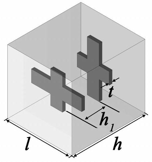
[0038] The invention proposes a method for realizing unidirectional enhanced photon spin Hall effect displacement, based on the Fabry-Perot cavity to realize the local characteristics of the light field to achieve non-resonant and near-zero Brewster angle, and by changing the cavity Adjustability of working frequency can be realized for a long time; by analyzing and calculating the formula of SHE displacement, the metasurface is used to regulate the Fresnel reflection coefficient, eliminating high-order terms, reducing the denominator, thereby increasing the displacement; and based on S 4 Symmetry, realize the Brewster angle phenomenon of p and s linearly polarized light that occurs on different sides of the metasurface, and then realize the unidirectionally enhanced SHE effect. Specifically include the following steps:

[0039] Step 1: Build with S 4 A symm...


PUM


Abstract

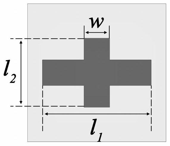
The invention discloses a method for realizing unidirectionally enhanced photon spin Hall effect displacement, and constructs a 4 Symmetrical metasurface, including the outer glass with a dielectric constant of 2.25 and the embedded two silver crosses with a dielectric constant conforming to the Drude model. The front silver cross has long and short arms, and the rear silver cross and front silver cross have dimensions Same, is the front end silver cross for C 4 After rotation, it is obtained by the mirror symmetry of the glass center plane, and a Fabry-Perot cavity is formed between the two silver crosses; based on S 4 Symmetry, realize the Brewster angle phenomenon of p and s linearly polarized light that occurs on different sides of the metasurface, and then realize the one-way enhanced SHE effect; analyze the formula for calculating the SHE displacement, and use the metasurface to calculate the Fresnel reflection coefficient The adjustment of the Fresnel coefficient eliminates the high-order term and increases the displacement. The invention breaks the limitation of the enhanced SHE effect on the polarization state, realizes the unidirectional enhanced photon SHE effect of the two ports on the front and back sides, and enhances the lateral displacement of the photon spin Hall effect.

Description

technical field [0001] The invention belongs to the field of optical microstructures, and in particular relates to a method for realizing unidirectionally enhanced photon spin Hall effect (spin Hall effect, SHE) displacement. Background technique [0002] As an analog of the electron spin Hall effect in a photonic field, the photonic spin Hall effect is attributed to the spin-orbit coupling of light, which leads to a spin-dependent displacement at the interface. When a linearly polarized beam is reflected or refracted at a plane interface, it will be laterally divided into left circular polarization (LCP) and right circular polarization (RCP) due to the opposite spin direction. Therefore, photonic SHEs open up a new possibility to control the spin state of photons and have realized potential applications in various fields, such as spin-based spectrometers, photonic sensors, and precision measurements. Due to the weak light-medium interaction, the spin-dependent splitting is...

Claims


Application Information

Patent Timeline
Patent Type & Authority Patents(China)
IPC IPC(8): G02B5/30G02B27/00
CPCG02B5/3033G02B27/0012
Inventor 伏洋洋刘佳晴李潇刘友文
Owner NANJING UNIV OF AERONAUTICS & ASTRONAUTICS
Learn More