Supercharge Your Innovation With Domain-Expert AI Agents!

Feeding trough capable of being cleaned in turnover mode for animal husbandry

A flipping, animal husbandry technology, applied in the field of feeding tanks, can solve the problems of low practicability and difficult cleaning, and achieve the effect of reducing labor intensity and realizing automatic opening

Pending Publication Date: 2021-06-18
叶建德
View PDF5 Cites 1 Cited by
  • Summary
  • Abstract
  • Description
  • Claims
  • Application Information

AI Technical Summary

Problems solved by technology

[0004] In order to overcome the shortcomings of difficult cleaning and low practicability in the prior art, the technical problem to be solved is to provide an easy-to-clean, high-practicability reversible cleaning feeding tank for animal husbandry

Method used


Image

  • Feeding trough capable of being cleaned in turnover mode for animal husbandry
  • Feeding trough capable of being cleaned in turnover mode for animal husbandry
  • Feeding trough capable of being cleaned in turnover mode for animal husbandry

Examples


Embodiment 1

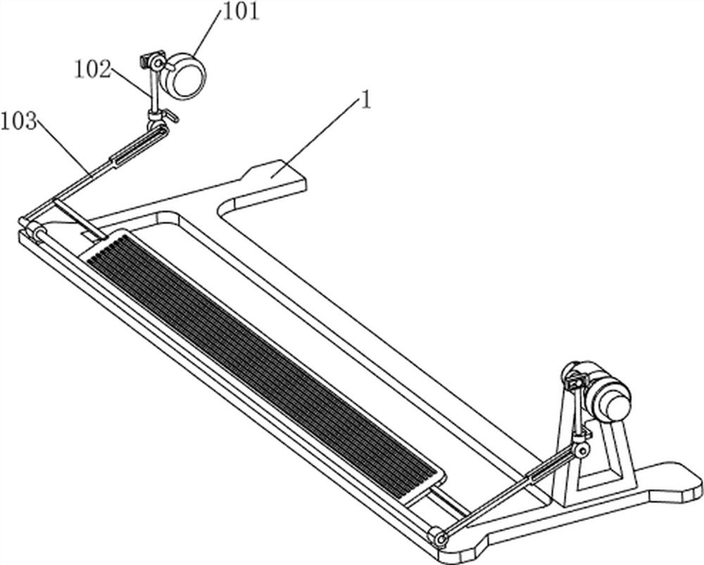
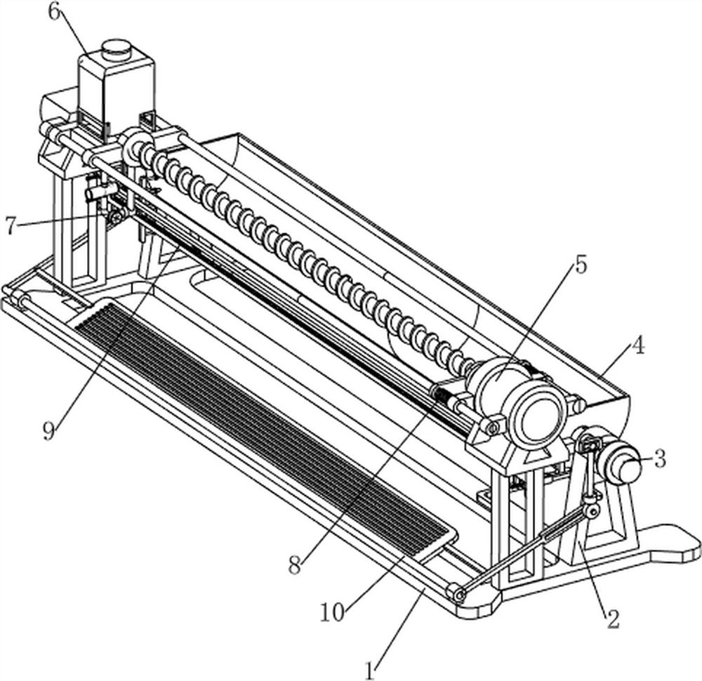
[0059] A feeding tank that can be flipped and cleaned in animal husbandry, such as Figure 1-5 As shown, it includes a base 1, a supporting platform 2, a rotating shaft 3, a breeding tank 4, a rotating mechanism 5, a storage mechanism 6 and a cleaning mechanism 7. The right side of the base 1 is symmetrically provided with a supporting platform 2, and the upper part of the supporting platform 2 is of a rotating type. A rotating shaft 3 is connected, and a rectangular hole is opened on the rotating shaft 3 on the front side. A breeding tank 4 is connected between the inner sides of the rotating shaft 3. A rotating mechanism 5 is provided on the left side of the base 1, and a storage mechanism 6 is arranged on the rotating mechanism 5 parts. , The storage mechanism 6 is provided with a cleaning mechanism 7.

[0060] When people need to feed livestock, they can use this device. People manually feed the feed in the feeding tank 4 for the livestock to eat. After eating, people put ...

Embodiment 2

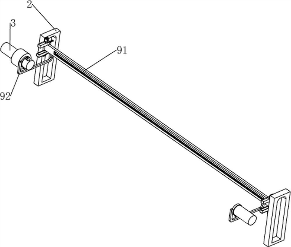
[0066] On the basis of Example 1, such as Figure 6-10 As shown, a clamping mechanism 8 is also included, and the clamping mechanism 8 includes a second bracket 81, a fixed frame 82, a first compression spring 83, a clamp rod 84 and a second compression spring 85, and the first bracket 51 on the front side is left A second bracket 81 is provided on the side, and a fixed frame 82 is provided on the upper right side of the second bracket 81. A toggle block is slidably connected between the front sides of the slide bar 54, and a toggle block is connected with the first bracket 51 on the front side. 2 first compression springs 83, the fixed frame 82 is slidingly connected with a clamping rod 84, the clamping rod 84 is in contact with the rotating shaft 3 on the front side, and the second compression spring is connected between the right side of the clamping rod 84 and the left side of the fixed frame 82 Spring 85.

[0067] People manually rotate the rotating shaft 3, and when the...


PUM


Abstract

The invention relates to a feeding trough, in particular to a feeding trough capable of being cleaned in a turnover mode for animal husbandry. The technical problem to be solved is to provide the feeding trough capable of being cleaned in the turnover mode for the animal husbandry, which is convenient to clean and high in practicability. According to the technical scheme, the feeding trough capable of being cleaned in the turnover mode for the animal husbandry comprises a base, supporting tables, rotating shafts, a feeding trough, a rotating mechanism, a storage mechanism and a cleaning mechanism; the supporting tables are symmetrically arranged on one side of the base; the rotating shafts are rotationally connected to the supporting tables; the feeding trough is connected between one sides of the rotating shafts; the rotating mechanism is arranged on one side of the base; the storage mechanism is arranged on a rotating mechanism component; the cleaning mechanism is arranged on a storage mechanism component. Through cooperation of a clamping mechanism and a treading mechanism, people do not need to manually rotate the rotating shafts, the rotating shafts are kept until the feeding trough is cleaned, and the labor intensity of people can be reduced.

Description

technical field [0001] The invention relates to a feeding tank, in particular to a reversible and washable feeding tank for animal husbandry. Background technique [0002] Animal husbandry uses livestock and poultry to convert plant energy such as forage and feed into animal energy through artificial feeding and breeding. Now in animal husbandry, feed and water for livestock must be fed in separate containers, resulting in a large space occupation. Moreover, it is more difficult to clean the current feed basins. The traditional cleaning method is to clean manually with the help of tools. There are many breeding tanks in animal husbandry, and the amount of manual cleaning is large, and it takes a long time. Easily picks up an unpleasant odor. [0003] Therefore, need to research and develop a kind of rearing tank that is easy to clean, the high practicability animal husbandry that can be flipped and cleaned. Contents of the invention [0004] In order to overcome the shor...

Claims


Application Information

Patent Timeline
IPC IPC(8): A01K5/01A01K39/014B08B9/093
CPCA01K5/01A01K39/014B08B9/093
Inventor 叶建德
Owner 叶建德
Features
  • R&D
  • Intellectual Property
  • Life Sciences
  • Materials
  • Tech Scout
  • Unparalleled Data Quality
  • Higher Quality Content
  • 60% Fewer Hallucinations
Learn More