
CNC stationary shaft shoulder mounting structure, friction stir welding tool and welding equipment

A technology of static shaft shoulder and installation structure, applied in welding equipment, non-electric welding equipment, metal processing equipment, etc., can solve the problems of inability to provide upsetting force, welding quality problems, etc., to reduce heat sink, improve welding quality, increase The effect of welding upsetting force

Pending Publication Date: 2021-06-18
昆山万洲特种焊接有限公司
View PDF2 Cites 0 Cited by
  • Summary
  • Abstract
  • Description
  • Claims
  • Application Information

AI Technical Summary

Problems solved by technology

However, in this method, the auxiliary shoulder is connected by elastic structures such as springs, which cannot provide a good upsetting force to compress the material. At the same time, the patent proposes that only approximately zero inclination welding can be achieved, and there are also certain welding quality problems in real non-inclination welding.

Method used


Image

  • CNC stationary shaft shoulder mounting structure, friction stir welding tool and welding equipment
  • CNC stationary shaft shoulder mounting structure, friction stir welding tool and welding equipment
  • CNC stationary shaft shoulder mounting structure, friction stir welding tool and welding equipment

Examples


Embodiment 1

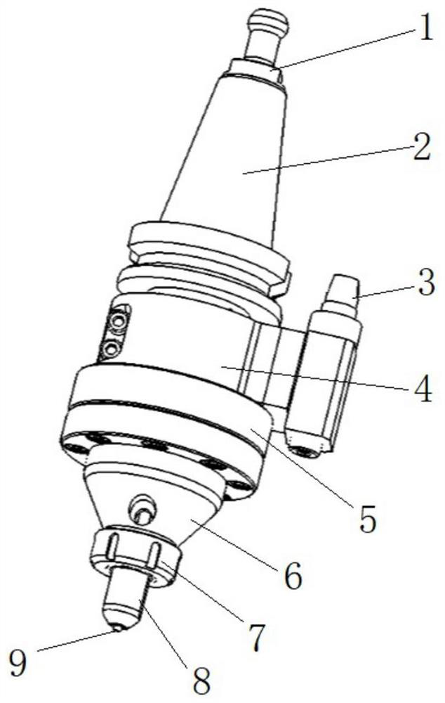
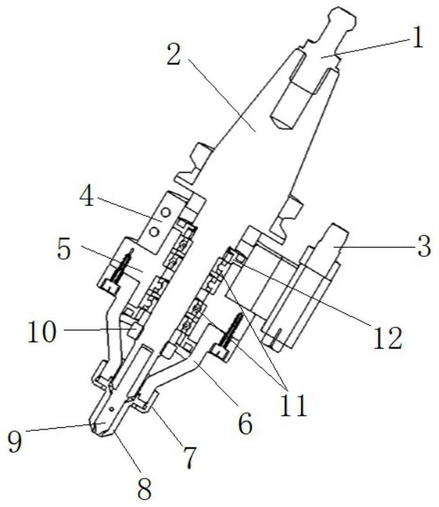
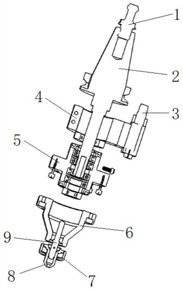
[0039] Such as Figure 1-4 As shown, this embodiment provides a CNC static shoulder installation structure, which can realize static shoulder friction stir welding on CNC equipment. Compress the material before welding to prevent the material from being scooped up. At the same time, the static shoulder is beneficial to reduce the heat sink, increase the welding upsetting force, and then improve the welding quality; and the structure is easy to install, the manufacturing cost is low, and the equipment can be reduced. purchase cost.

[0040]The CNC static shoulder installation structure provided in this embodiment includes a knife handle 2, a support ring 5, a shaft sleeve 6, a static shoulder 8 and a stirring needle 9; End, and have the working end that is suitable for installing stirring needle 9; Wherein, as Figure 1-3 As shown, the mounting end preferably has a tapered structure, and further, the top of the tapered structure can be provided with a pull stud 1; the pull st...

Embodiment 2

[0049] This embodiment provides a friction stir welding tool and friction stir welding equipment, which include CNC equipment and the static shoulder mounting structure described in Embodiment 1. The friction stir welding tool further includes a stationary shoulder and a stirring pin, wherein the stationary shoulder is mounted on the bottom of the bushing, and the stirring pin is mounted on the working end of the handle. The tool handle installation end of the static shoulder mounting structure is installed in the tool handle mounting hole of the CNC equipment; the static shoulder friction stir welding can be realized on the CNC through the friction stir welding welding tool, and the static shoulder can be in the Press the material before welding to prevent the material from being "shoveled". At the same time, the static shoulder is beneficial to reduce heat sink, increase welding upsetting force, and improve welding quality.

[0050] In addition, the friction stir welding equ...


PUM


Abstract

The invention relates to the technical field of friction stir welding, in particular to a CNC stationary shaft shoulder mounting structure, a friction stir welding tool and welding equipment. The stationary shaft shoulder mounting structure comprises a cutter handle, a supporting ring and a shaft sleeve, and the cutter handle is provided with a mounting end suitable for being mounted on CNC equipment and a working end suitable for mounting a stirring needle; and at least one bearing is arranged in the supporting ring, the bearing is arranged at the outer side of the cutter handle in a sleeving manner, and the bearing is in transition fit with the supporting ring. According to the stationary shaft shoulder mounting structure, at the outer side of the rotating cutter handle used by the CNC equipment, the shaft sleeve is directly or indirectly connected to the cutter handle through the bearing in the supporting ring, relative rotation between the cutter handle and the shaft sleeve is achieved, then support is provided for follow-up mounting of a stationary shaft shoulder, friction stir welding of the stationary shaft shoulder can be achieved on the CNC equipment, materials are pressed tightly before welding, the materials are prevented from being shoveled up, meanwhile, the stationary shaft shoulder is beneficial to reducing heat sink and increasing welding upsetting force, then the welding quality is improved, and the equipment purchasing cost is reduced.

Description

technical field [0001] The invention relates to the technical field of friction stir welding, in particular to a CNC static shoulder installation structure, friction stir welding tools and welding equipment. Background technique [0002] As an advanced welding technology, friction stir welding has the characteristics of high welding strength, green and pollution-free. During the welding process, the rotating stirring head plunges into the plate to be welded and moves along the direction of the welding seam to realize welding. At present, the equipment for realizing this welding method includes special friction stir welding machine tools, friction stir welding robots and other welding equipment. However, these devices are expensive and are not suitable for large-scale purchases by small machinery processing plants. [0003] The friction stir welding welding process is similar to the CNC machining process, and the friction stir welding can be realized by simply modifying the...

Claims


Application Information

Patent Timeline
IPC IPC(8): B23K20/12
CPCB23K20/1255
Inventor 万龙袁玉亮温琦黄体方
Owner 昆山万洲特种焊接有限公司
Learn More