

Positioning and clamping tool for aircraft part machining
A technology for clamping tooling and parts, applied in workpiece clamping devices, manufacturing tools, etc., can solve problems such as scratches on the surface of parts and uneven bottoms of parts, so as to reduce costs, avoid shaking, and avoid equipment accuracy. Effect
- Summary
- Abstract
- Description
- Claims
- Application Information
AI Technical Summary
Problems solved by technology
Method used
Image

Examples
Embodiment
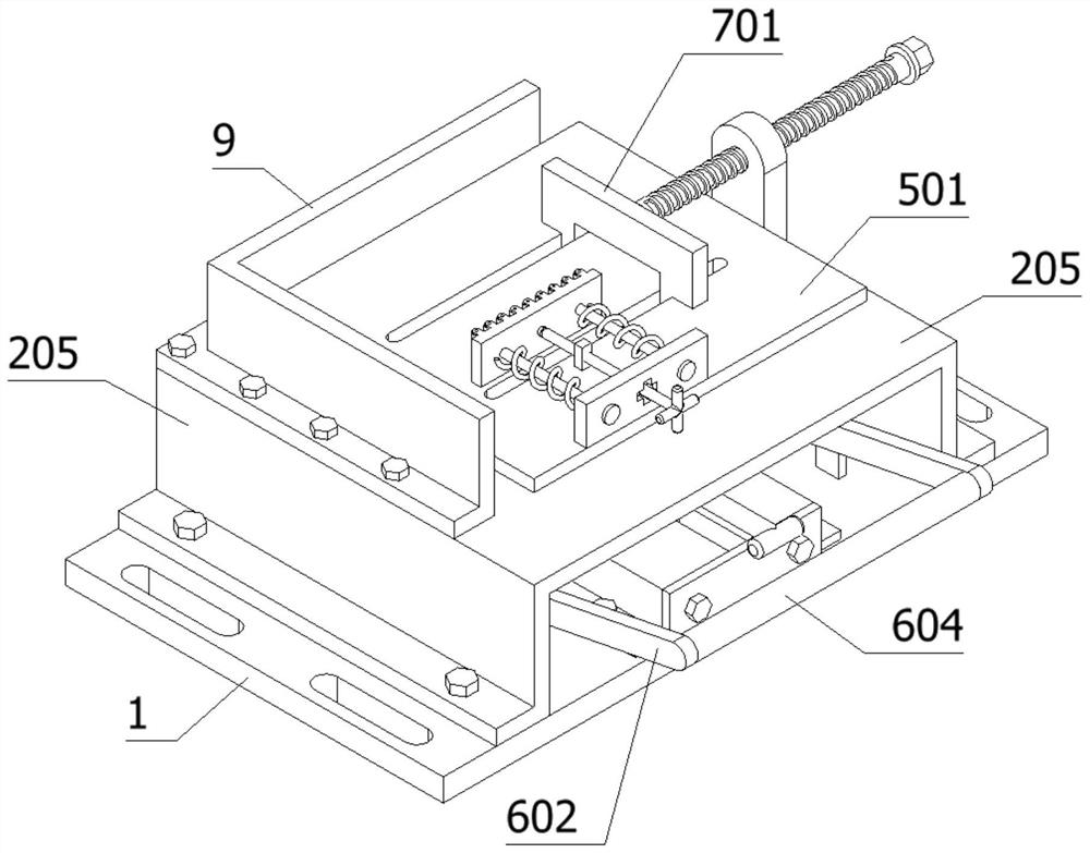
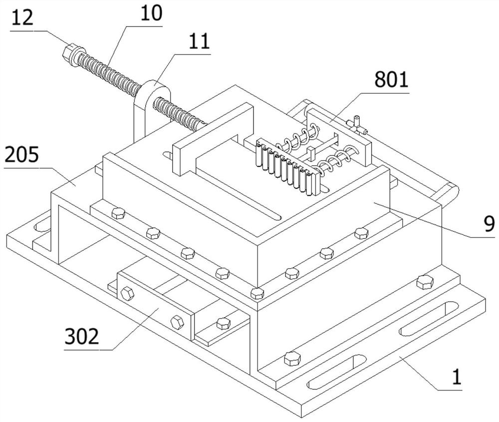
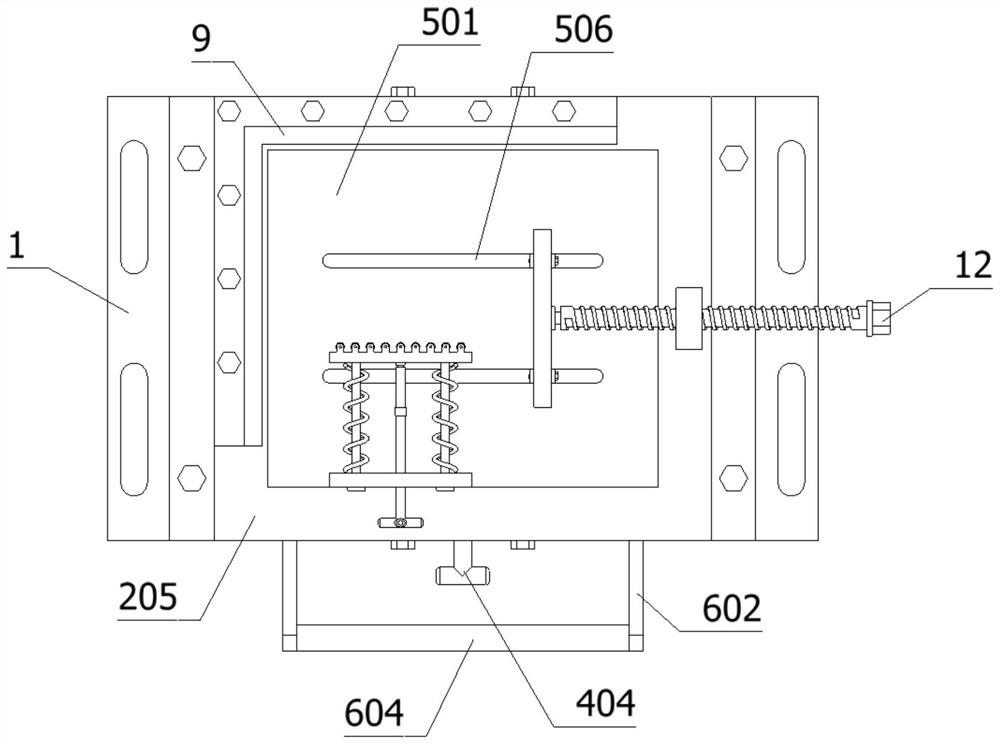
[0033] as attached figure 1 to attach Figure 7 Shown:
[0034] The invention provides a positioning and clamping tool for processing aircraft parts, including a base plate 1, a fixing device 3, a lifting structure 5, a clamping device 7, a positioning device 8, and a screw rod 10; the top of the base plate 1 is fixed with a mounting structure by screws 2. The installation structure 2 also includes a through groove 201, a limit hole 202, a chute 203, a through hole 204 and a mounting plate 205; four limit holes 202 are opened inside the mounting plate 205, and the center of the mounting plate 205 is opened There is a through hole 204; the mounting plate 205 is left and right symmetrically penetrated and provided with a through groove 201, and the mounting plate 205 is provided with a chute 203 symmetrically front and rear; the top of the mounting plate 205 is fixed with a fixed plate 9 by screws; The center position of the top of the bottom plate 1, and the sliding device 4 ...
PUM
 Abstract
Description
Claims
Application Information