Supercharge Your Innovation With Domain-Expert AI Agents!

Closing cap for stamp and stamp therefor

A closed cover and seal technology, which is applied in printing, stamping and other directions, can solve the problem of snapping and locking hooks breaking, and achieve the effect of reliable release

Pending Publication Date: 2021-06-18
TRODAT GMBH
View PDF17 Cites 2 Cited by
  • Summary
  • Abstract
  • Description
  • Claims
  • Application Information

AI Technical Summary

Problems solved by technology

[0008] A disadvantage of the closure cap described above is that the closure cap can only be pulled out of the stamp with increased force expenditure in order to release the closure
It can happen here that due to the deformation of the detent hook, the detent hook breaks off or no longer returns to the original position and thus no longer provides a secure hold for the closure cap.

Method used


Image

  • Closing cap for stamp and stamp therefor
  • Closing cap for stamp and stamp therefor
  • Closing cap for stamp and stamp therefor

Examples


Embodiment Construction

[0062] First, the same components as those in different figures are provided with the same reference numerals or the same component name, wherein the disclosure included in the entire specification can be diverted to the same reference numeral or the same component name. On the same part. In the description, the description, such as,,,,,,,,,,,,,,,,,,,,,,,,,,,,,,,,,,,,,,,,,,,,,, The single feature or feature combination of the illustrated embodiments itself may also form an independent creative solution.

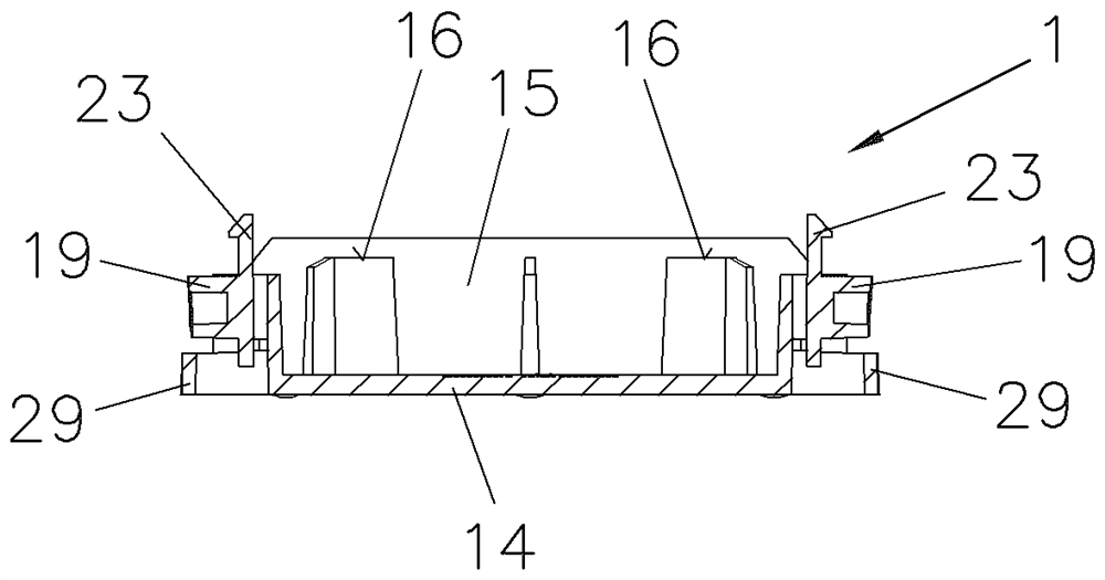
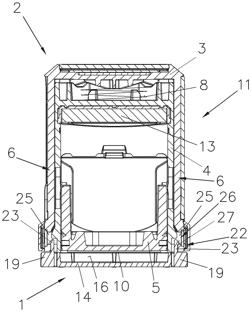
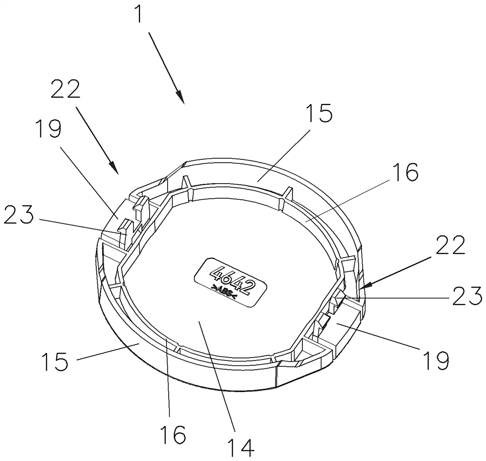
[0063] in Figure 1 to 8 It is shown in the seal 2, especially for the sealing cover 1 for self-colored seal 2.

[0064]The seal 2 includes at least one upper member 3, the lower member 4, and the molding unit 5, wherein the printing unit 5 is coupled or coupled to the upper member 3 via the inverting mechanism 6, in particular by the slot rail 7 in the lower member 4. Further, a spring element 8 for reset to the stationary position 9 is disposed between the upper member 3 and the...


PUM


Abstract

The invention describes a closure cap for a stamp (2), in particular a self-inking stamp (2), a stamp device and a stamp (1), the stamp comprising at least one plate-shaped cover cap (14) or cover surface (14) with protruding side walls (15) and preferably at least one internal support element (16) for a lower part (4) of the stamp (1). Two opposite actuating elements (19) are arranged on the outer circumference of the cover cap (14), at least one actuating element (19) being flexibly or elastically connected to the cover cap (14) or the side walls (15), each actuating element (19) at least having a latching element (22), in particular a latching hook (23), for hooking into a latching lug in the internal space (15) or free space (25) of an upper part (3) of the stamp (2) or is connected to the latching lug.

Description

Technical field [0001] The present invention relates to a seal and seal for this in accordance with the present invention. Background technique [0002] From the WO 2016 / 197172 A1 discloses a seal, in particular a frame (Stativ) seal, which comprises at least one stamping unit and the platen assembly, wherein the upper platen assembly and configured arcuate member having a stamp pad receiving element (Kissenaufnahmeelement The lower part is formed. Preferably by stamping unit reversing mechanism having a sliding rail connection connected to the moving member via a shaft journal or the lower part, wherein, in the static part, the mounting plate in the stamping characters rests against the ink pad unit receiving element Using a printing of the printing oil. During the imprinting process used to generate the imprinting, the molding unit having the text panel is adjusted to the imprint position via the inverting mechanism. Furthermore, a closed cover is shown by a narrow side to the ...

Claims


Application Information

Patent Timeline
Patent Type & Authority Applications(China)
IPC IPC(8): B41K1/02B41K1/36B41K1/58
CPCB41K1/36B41K1/40B41K1/02B41K1/58
Inventor O·曼福雷德L·海姆特
Owner TRODAT GMBH
Features
  • R&D
  • Intellectual Property
  • Life Sciences
  • Materials
  • Tech Scout
  • Unparalleled Data Quality
  • Higher Quality Content
  • 60% Fewer Hallucinations
Learn More