A double-layer self-circulating pressure-holding grouting pipe

A grouting pipe, environmental protection technology, applied in soil protection, construction, infrastructure engineering and other directions, can solve the problems of poor grouting uniformity, poor stability of grouting pipe, etc., to reduce vibration, avoid vibration, and improve uniformity. Effect

Active Publication Date: 2022-03-15
CHINA RAILWAY ENG CONSULTING GRP CO LTD
View PDF6 Cites 0 Cited by
  • Summary
  • Abstract
  • Description
  • Claims
  • Application Information

AI Technical Summary

Problems solved by technology

[0005] The purpose of the present invention is to provide a double-layer self-circulating pressure-maintaining grouting pipe to improve the defects of poor stability and poor grouting uniformity of the grouting pipe. In order to achieve the above object, the technical scheme adopted by the present invention is as follows:

Method used


Image

  • A double-layer self-circulating pressure-holding grouting pipe
  • A double-layer self-circulating pressure-holding grouting pipe
  • A double-layer self-circulating pressure-holding grouting pipe

Examples


Embodiment approach 1

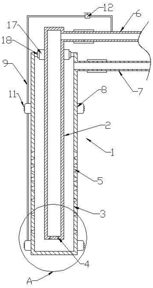
[0042] Such as Figure 1 to Figure 3 As shown, this embodiment provides a double-layer self-circulating pressure-maintaining grouting pipe, including a grouting pipe 1, and the grouting pipe 1 includes an inner pipe 2 and an outer pipe 3, and the upper part of the inner pipe 2 is fixedly provided with a fixed Disk 17, the two ends of the outer tube 3 are open structures, and the upper open end is provided with a fixing ring 18, and the fixing disk 17 is connected with the fixing ring 18 with a screw, so that the outer tube 3 is placed on the outer surface of the inner tube 2; The top of the inner pipe 2 is connected to the communication pipe 6, and the upper part of the side wall of the outer pipe 3 is connected to the circulation pipe 7, and the communication pipe 6 and the circulation pipe 7 are connected to the external grouting equipment, thereby forming a closed circulation loop;

[0043] The bottom surface of the inner tube 2 is evenly provided with a plurality of commun...

Embodiment approach 2

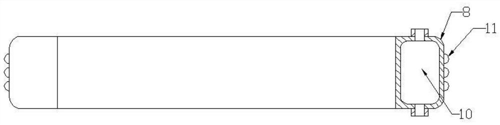
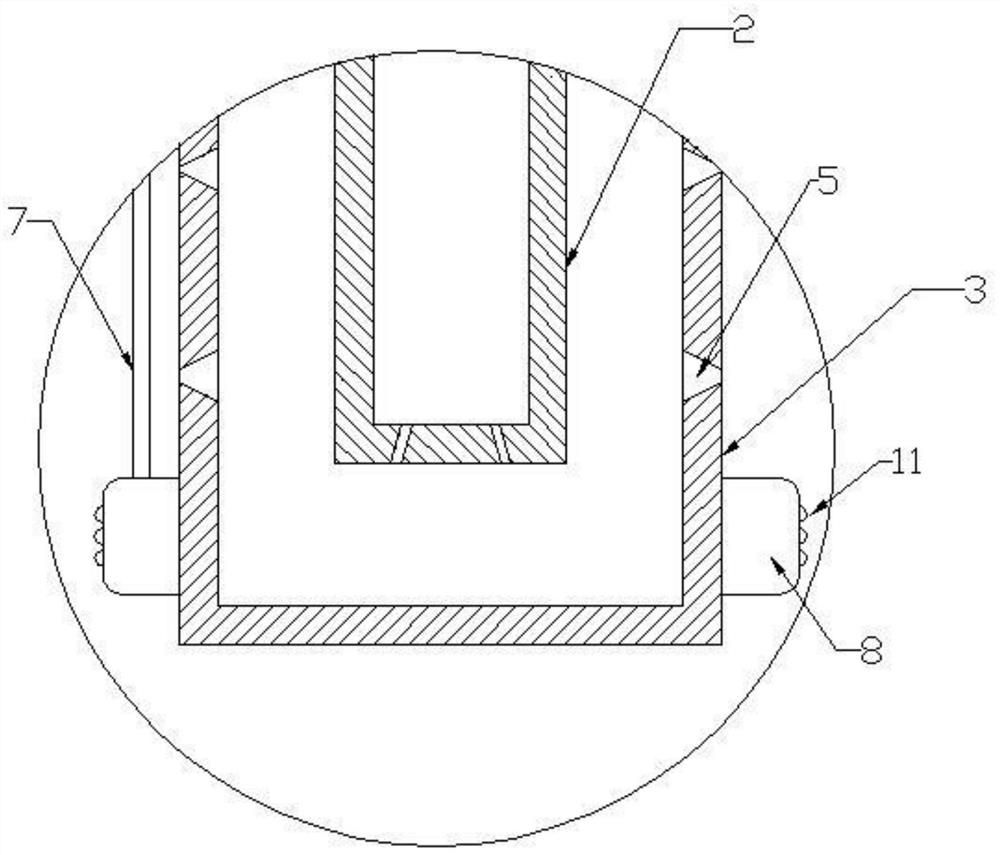
[0046] Such as Figure 4 and Figure 5 As shown, this embodiment discloses a double-layer self-circulating pressure-maintaining grouting pipe on the basis of Embodiment 1, including an inner pipe 2 and an outer pipe 3, the bottom of the outer pipe 3 is an open structure, and the outer pipe The open end of the bottom of 3 is sealed by the diversion cover 13 connected by thread, the outer edge of the diversion cover 13 is provided with an arc-shaped second diversion surface 14, and the center of the diversion cover 13 is provided with the top and the bottom surface of the inner tube 2 The abutting split column 15 is provided with an arc-shaped first flow guide surface 16 on the side of the split column 15 , and the first flow guide surface 16 is smoothly connected with the second flow guide surface 14 .

[0047] When the present invention is used, the external grouting equipment pressurizes the prepared slurry from the connecting pipe into the inner pipe, and enters the outer p...


PUM


Abstract

The invention relates to a double-layer self-circulation pressure-maintaining grouting pipe, comprising a grouting pipe, wherein the grouting pipe comprises an inner pipe and an outer pipe that are sleeved with each other, the inner pipe and the outer pipe are communicated with each other, and the outer pipe is provided with an outlet pipe. At the same time, the inner pipe and the outer pipe are respectively connected with the grouting pump through the communication pipe and the circulation pipe; at the same time, an expansion sleeve is also sleeved on the outer pipe, and the expansion sleeve is connected with the communication pipe through the expansion pipe; when the present invention is used, the slurry first enters The inner pipe enters the outer pipe from the inner pipe, and finally grouting into the soil layer from the slurry outlet; it buffers the slurry through the design of the inner and outer pipes, thereby reducing the pressure variation and vibration amplitude of the slurry; The adjustment of the pore size and distribution density of the grouting pipe leads to the drainage to the far end of the grouting pipe, so as to ensure the uniform distribution of the grouting; Vibration of the tube to improve the grouting quality.

Description

technical field [0001] The invention relates to the technical field of rock and soil construction, in particular to a double-layer self-circulating pressure-maintaining grouting pipe. Background technique [0002] The grouting method is to use the pressure (hydraulic pressure, air pressure) or electrochemical principle to uniformly inject the grout with gel ability into the gaps, cracks and cavities in the soil layer (or rock layer) through drilling holes, and the grout can fill, infiltrate and The original loose and broken rock (soil) layer is cemented into a whole by means of extrusion, and the physical and mechanical properties of the rock (soil) layer (such as the permeability of rock and soil layers, The strength and bearing capacity of rock and soil layers, the deformation of rock and soil layers, etc.) can be improved to form a structure with new structure, high strength, high waterproof performance and good chemical stability to meet various civil engineering project...

Claims


Application Information

Patent Timeline
Patent Type & Authority Patents(China)
IPC IPC(8): E02D3/12
CPCE02D3/12
Inventor 蒋小锐刘建友刘方岳岭吕刚谭富圣马福东金张澜孟超邬泽黄杰陈丹李锴彭斌王杨郭磊陈慧李力张延张矿三王文谦徐品章
Owner CHINA RAILWAY ENG CONSULTING GRP CO LTD
Why Eureka
Try Eureka