A drive system of vva solenoid valve with close detection function
A solenoid valve driving, solenoid valve technology, applied to non-mechanically actuated valves, valve devices, engine components, etc., can solve the problems of inaccurate driving process and inconsistent performance of solenoid valves, so as to improve fuel economy and ensure power. performance, improve idle speed stability
- Summary
- Abstract
- Description
- Claims
- Application Information
AI Technical Summary
Problems solved by technology
Method used
Image

Examples
Embodiment Construction
[0042] The following is a clear and complete description of the technical solutions in the implementation of the present invention in conjunction with the accompanying drawings, and the described embodiments are only part of the embodiments of the present invention, not all of them. Based on the embodiments of the present invention, all other embodiments obtained by persons of ordinary skill in the art without making creative efforts fall within the protection scope of the present invention.
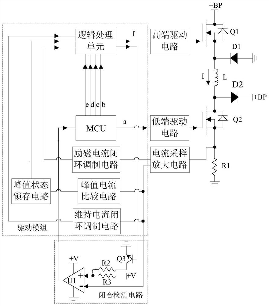
[0043] Such as Figure 2 to Figure 5 As shown, a kind of VVA solenoid valve driving system with closing detection function provided by the present invention includes:
[0044] VVA solenoid valve L, one end is connected to the power supply +BP through the high-end transistor Q1, and the other end is grounded through the low-end transistor Q2 and the sampling resistor R1 in turn, and the common end of the high-end transistor Q1 and the VVA solenoid valve L is connected to the first diode ...
PUM
 Abstract
Description
Claims
Application Information
 - R&D
- Intellectual Property
- Life Sciences
- Materials
- Tech Scout
- Unparalleled Data Quality
- Higher Quality Content
- 60% Fewer Hallucinations
Browse by: Latest US Patents, China's latest patents, Technical Efficacy Thesaurus, Application Domain, Technology Topic, Popular Technical Reports.
© 2025 PatSnap. All rights reserved.Legal|Privacy policy|Modern Slavery Act Transparency Statement|Sitemap|About US| Contact US: help@patsnap.com