Shafting transverse vibration large force value inertia type electromagnetic active control device

A technology of lateral vibration and active control, applied in propulsion transmission, non-rotational vibration suppression, propulsion power transmission, etc., can solve the problems of small harmonic distortion, low output force value, difficult installation, etc., and achieve good linearity, Large output force, two-way force and easy effect

Pending Publication Date: 2021-06-18
WUHAN UNIV OF TECH
View PDF6 Cites 2 Cited by
  • Summary
  • Abstract
  • Description
  • Claims
  • Application Information

AI Technical Summary

Problems solved by technology

There are two kinds of electromagnetic actuators, one is the traditional ejector type vibrator, the disadvantage is that it is not easy to install, and the other is the inertial actuator, which is easy to install, has good linearity, small harmonic distortion, and is easy to control low-frequency lines. Spectrum
The current electromagnetic inertial actuator still has the problems of low output force value per unit volume weight and poor reliability

Method used


Image

  • Shafting transverse vibration large force value inertia type electromagnetic active control device
  • Shafting transverse vibration large force value inertia type electromagnetic active control device
  • Shafting transverse vibration large force value inertia type electromagnetic active control device

Examples


Embodiment 1

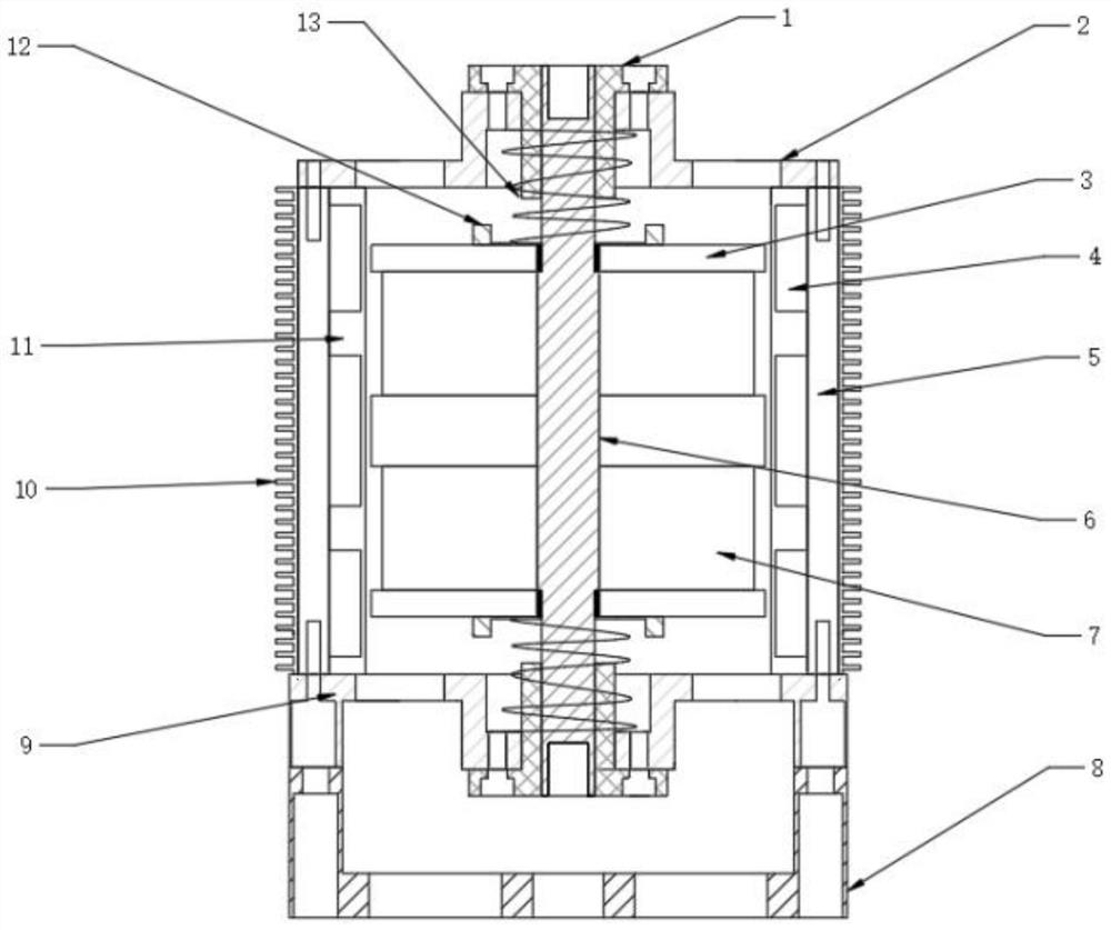
[0027] A large value inertial electromagnetic active control device for shafting lateral vibration, see Figure 1-8 , the device comprises: a magnetically conductive shell 5, an upper end cover 2 and a lower end cover 9 fixed on both ends of the magnetically conductive shell 5, a wire frame 11 arranged in the magnetically conductive shell 5, a spring radial fixing member 12, a coil 4, and a magnetically conductive body 3. The non-magnetic main rod 6, the permanent magnet 7, the compression spring 13, and the base 8 fixed on the lower end cover 9.

[0028] The non-magnetic main rod 6 is at the central axis of the magnetic shell 5, and its two ends are rotatably connected with the upper end cover 2 and the lower end cover 9 by bearings 1 fixed (as bolts) on the upper end cover 2 and the lower end cover 9 respectively. The base 8 is fixed on the outer ring of the bearing 1 and the lower end cover 9, and the base 8 and the lower end cover 9 are fixed (such as welded) to play a sup...


PUM


Abstract

The invention discloses a shafting transverse vibration large force value inertia type electromagnetic active control device. The device comprises a magnetic conductive shell, an upper end cover, a lower end cover, a wire frame, a spring radial fixing piece, a coil, magnetizers, a non-magnetic-conductive main rod, permanent magnets, a compression spring and a base, wherein the upper end cover and the lower end cover are fixed to the two ends of the magnetic conductive shell, and the wire frame, the spring radial fixing piece, the coil, the magnetizers, the non-magnetic-conductive main rod, the permanent magnets and the compression spring are arranged in the magnetic conductive shell. The base is fixed on the lower end cover. The main rod, the permanent magnets and the magnetizers form a rotor. The main rod is located on the central axis of the magnetic conductive shell, and two ends of the main rod are rotationally connected with the upper end cover and the lower end cover through bearings respectively. The permanent magnets and the magnetizers are alternately arranged on the outer side wall of the main rod in the axial direction of the main rod, the magnets located at the two ends are the magnetizers, the same poles of the adjacent permanent magnets are opposite, and the permanent magnets and the magnetizers located at the two ends of the permanent magnets form a closed magnetic circuit through the magnetic conductive shell. According to the device, the mover output force and the shafting vibration direction are opposite and the frequency is the same by adjusting the electrifying frequency and direction of the coil, so that the shafting transverse vibration is controlled.

Description

technical field [0001] The invention relates to an electromagnetic active control device, in particular to an inertial electromagnetic active control device with large lateral vibration of a shaft system. Background technique [0002] Shafting is the main equipment for power transmission. It effectively connects the main engine and executive parts (such as oars) and forms a complete power system to make the equipment (such as ships) run normally. When the main force transmission of the shaft system is uneven, the torque and installation cannot be centered, and the material processing is inaccurate, etc., the shaft system will be in an unbalanced state and lateral vibration will occur (in addition, the propeller in the uneven flow field work, it will cause disturbance at the tail of the ship, causing resonance and local vibration of the ship). Severe lateral vibration may cause excessive bending stress of the shafting, causing it to break and endangering human life. [0003...

Claims


Application Information

Patent Timeline
Patent Type & Authority Applications(China)
IPC IPC(8): F16F15/03F16F15/04B63H23/00
CPCB63H23/00F16F15/03F16F15/04
Inventor 张聪刘渊之国玉阔章林柯杨磊
Owner WUHAN UNIV OF TECH
Why Eureka
Try Eureka